Mirror-Embedded Optical Waveguide and Fabrication Method of Same

a technology of optical waveguides and fabrication methods, applied in optical waveguide light guides, instruments, optics, etc., can solve the problems of increased light reflection loss, degraded reflection efficiency, and cost problems of mirrors provided by metal-deposited surfaces, and achieve excellent optical characteristics and reliability, and advantages in cost and mass production

Inactive Publication Date: 2009-02-19
HITACHI CABLE
View PDF14 Cites 62 Cited by
  • Summary
  • Abstract
  • Description
  • Claims
  • Application Information

AI Technical Summary

Benefits of technology

[0019]The present invention exhibits excellent advantages as follows.
[0020](1) It offers a mirror-embedded optical waveguide having excellent optical characteristics and reliability.
[0021](2) It offers a fabrication method for a mirror-embedded optical waveguide having advantages in terms of cost and mass production.

Problems solved by technology

However, the mirror utilizing the bare surface cut by dicing or the like has a surface roughness (projections and depressions), and therefore has a problem of increased light reflection loss (mirror loss) due to degraded reflection efficiency.
On the other hand, the mirror provided by the metal-deposited surface has a cost problem because the number of waveguides loadable in a vapor deposition chamber becomes limited with increasing size of the waveguide.
Such use of a mask presents problems of increased cost and resolution limitation.
Furthermore, a vapor-deposited metal film generally has a poor adhesiveness to an optical waveguide material, thus posing a problem of peeling.
However, when light is incident on and reflected by the core-side (waveguide-side) surface of such an above-described mirror of an optical waveguide, the light passes through such a TiO2 adhesive layer, thus causing a problem of reduced reflectivity.

Method used


Image

  • Mirror-Embedded Optical Waveguide and Fabrication Method of Same
  • Mirror-Embedded Optical Waveguide and Fabrication Method of Same
  • Mirror-Embedded Optical Waveguide and Fabrication Method of Same

Examples


example 1

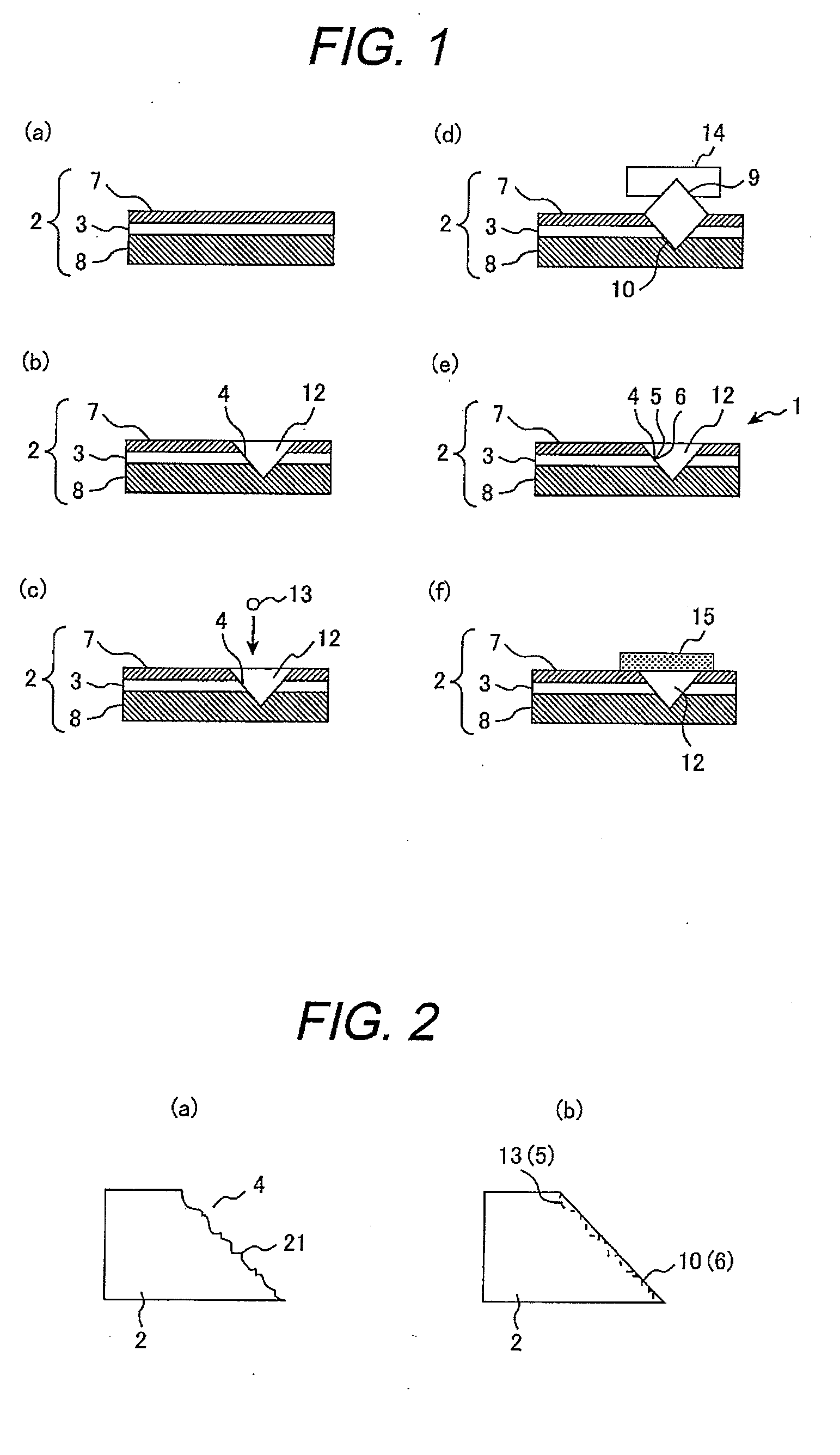
[0047]At first, in order to fabricate a mirror groove, a V-groove having cut faces angled 45° with respect to the axis of a photonic device was formed in an epoxy-based polymer optical waveguide [refractive index: 1.57 (core); 1.51 (clad)] using a dicing blade with two cutting faces forming a 90° angle. The structure of the epoxy-based polymer optical waveguide was as follows: core thickness 50 μm, underclad thickness 50 μm, overclad thickness 20 μm, without substrate.

[0048]Then, a metal-layer-transferring-jig was fabricated using a square column of silicon with smooth surfaces having a roughness Ra of 0.02 μm or less. Subsequently, a 0.3-μm-thick gold layer was vapor deposited onto the jig. Next, onto the core area of the mirror groove, there was dropped, with a dispenser, a thermosetting epoxy-based adhesive having the same refractive index as that of the core (1.57). Then, the metal-layer-transferring-jig was fitted into the mirror groove so that its gold deposited surface contac...

example 2

[0054]Another mirror-embedded-optical-waveguide as Example 2 was fabricated. In Example 2, a thermosetting epoxy-based adhesive having the refractive index of 1.52 was used, which was approximately the same refractive index as that of the core (1.57). The other fabrication conditions as well as the measurement were the same as those of Example 1.

[0055]The result of the measurement was that the light reflection loss (mirror loss) of Example 2 was as low as 0.7 dB, which was almost the same level in Example 1. In addition, there was observed no degradation in the light reflection loss (mirror loss) even after the high-temperature-and-high-humidity test (85° C. and 85% RH for 1,000 h) and after the thermal shock test (from −40° C. to 85° C., 500 cycles).

example 3

[0056]Another mirror-embedded-optical-waveguide as Example 3 was fabricated. In Example 3, a thermosetting epoxy-based adhesive having the refractive index of 1.60 was used, which was approximately the same refractive index as that of the core (1.57). The other fabrication conditions as well as the measurement were the same as those of Example 1.

[0057]The result of the measurement was that the light reflection loss (mirror loss) of Example 3 was as low as 0.6 dB, which was almost the same level in Example 1. In addition, there was also observed no degradation in the light reflection loss (mirror loss) even after the high-temperature-and-high-humidity test (85° C. and 85% RH for 1,000 h) and after the thermal shock test (from −40° C. to 85° C., 500 cycles).


PUM


Abstract

A mirror embedded optical waveguide according to the present invention comprises: a core; an angled cut face in the core; an adhesive layer on the angled cut face, the adhesive layer having approximately the same refractive index as that of the core; and a metal film on the adhesive layer, the metal film being formed by transfer.

Description

CLAIM OF PRIORITY[0001]The present application claims priority from Japanese patent application serial no. 2007-150466 filed on Jun. 6, 2007, the content of which is hereby incorporated by reference into this application.BACKGROUND OF THE INVENTION[0002]1. Field of the Invention[0003]The present invention relates to mirror-embedded optical waveguides and fabrication methods thereof, which offer excellent characteristics in terms of cost, mass production and reliability.[0004]2. Description of Related Art[0005]With recent development of information and communication technology typified by the Internet as well as dramatic increase in processor speeds, there has been growing demand for high volume data transmission such as image and motion video. In such high volume data transmissions, there is demand for transmission rates of 10 Gbps or more as well as small effect of electromagnetic noise. Among such high-speed communications, optical transmissions, which are not affected by electrom...

Claims


Application Information

Patent Timeline
Patent Type & Authority Applications(United States)
IPC IPC(8): G02B6/26
CPCG02B6/4214G02B6/1221
Inventor YASUDA, HIROKIHIRANO, KOKI
Owner HITACHI CABLE
Why Eureka
Try Eureka