Method for manufacturing the one body abutment of implant

a technology of implanted teeth and manufacturing methods, which is applied in the field of manufacturing artificial teeth, can solve the problems of tooth decay, awkward feeling in the oral cavity, gap at the portion of the abutment in contact with the gums, etc., and achieve the effect of improving strength

Inactive Publication Date: 2009-02-19
KIM JUNG HAN
View PDF6 Cites 34 Cited by
  • Summary
  • Abstract
  • Description
  • Claims
  • Application Information

AI Technical Summary

Benefits of technology

[0021]Furthermore, since the abutment is manufactured into a one body structure by a precision machine, it can have improved strength and be mass-produced.

Problems solved by technology

However, in the case of the casting method for abutment, due to the tolerance between the mold and the finished abutment, a gap occurs at the portion where the abutment is in contact with the gums.
Food becomes lodged in the gap, thus causing the tooth to be decayed or leading to an awkward feeling in the oral cavity.
In this manner, two materials are used, thus deteriorating the strength thereof, and the gold, which is expensive, imposes an economic burden on the patent.
However, the method disclosed in Patent Document 1 also cannot solve the fundamental problem in that it must be subjected to various procedures due to its nature, and in that it makes mass production impossible due to the long manufacturing period.
This cutting process is not only difficult but also time consuming, and also induces fear in the patient.
However, such an abutment structure has problems in that the load on a crown is directly delivered to the portion that is engaged with a screw, so that the engaged state of the screw is frequently loosened.
In severe cases, the screw itself is broken and escapes from the abutment.
Further, when a load is continuously applied to the abutment, for example, in response to repeated chewing, the slightest vibration can naturally loosen the screw from the implant fixture.
In such a case, the patient is required to undergo surgery again to receive a new implant, which causes pain and discomfort to the patient.
This is not only inconvenient and troublesome for both the patient and the doctor, but also causes an economic burden, which cannot be neglected.

Method used


Image

  • Method for manufacturing the one body abutment of implant
  • Method for manufacturing the one body abutment of implant
  • Method for manufacturing the one body abutment of implant

Examples


Embodiment Construction

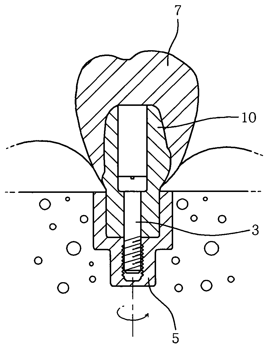
[0030]Hereinafter, a method of a one body abutment for a dental implant according to the present invention will be described more fully in conjunction with the accompanying drawings, in which exemplary embodiments thereof are shown.

[0031]The method of manufacturing a one body abutment 10 for a dental implant according to the invention generally includes steps of designing virtual teeth 30, designing the abutment 10 and forming the abutment 10.

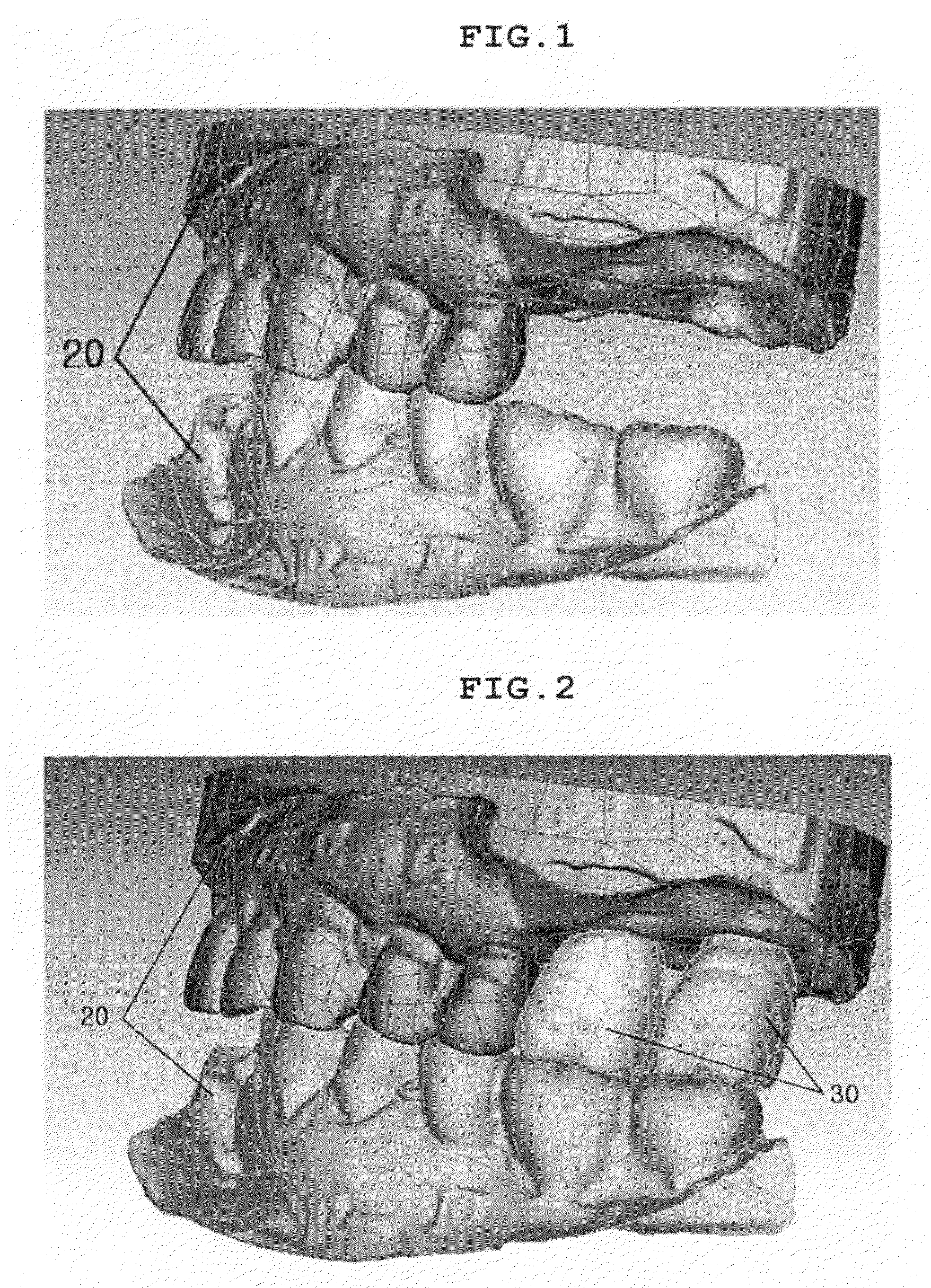
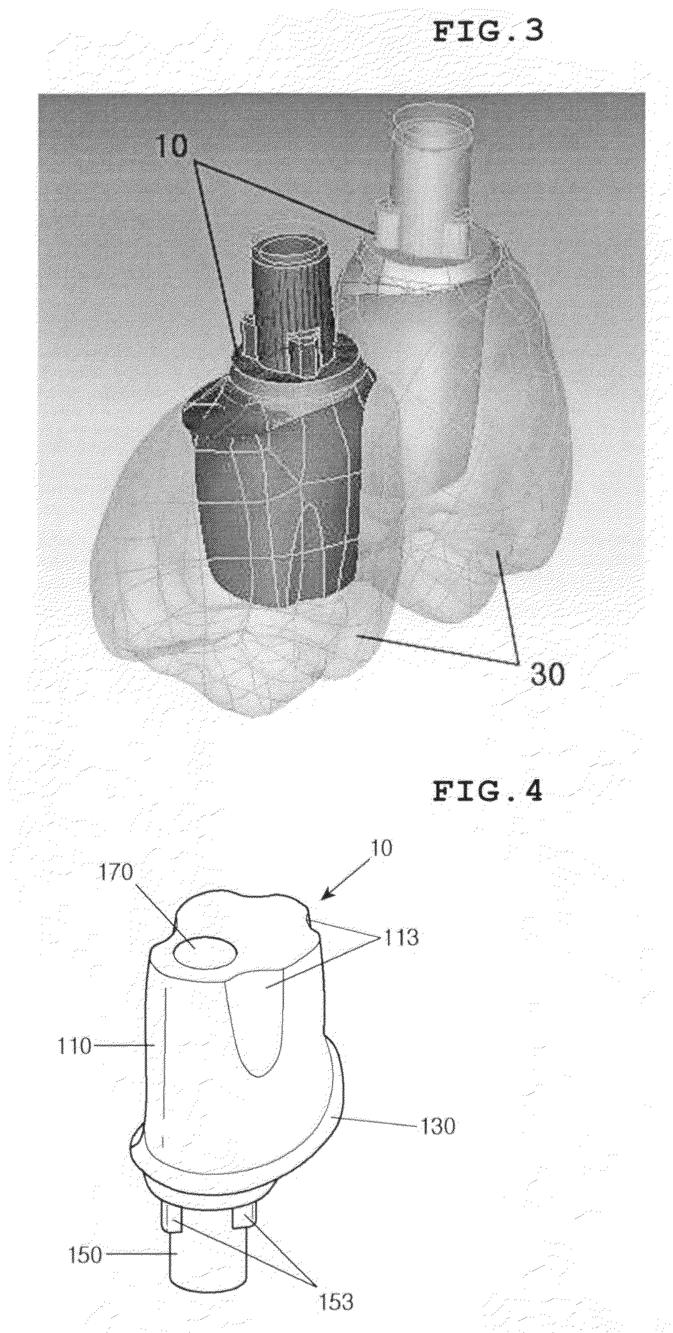
[0032]The first step is to design the virtual teeth 30. First, a three dimensional (3D) image 20 is created on a computer by performing 3D scanning on a dental plate of plaster, obtained from the oral cavity of a patient.

[0033]FIG. 1 shows the 3D image 20 created in this step. As shown in FIG. 1, the 3D image includes jawbones and teeth of the patient, so that correct data on the height, width, row and alignment of adjacent teeth and the shape of the gums can be obtained from the 3D image. Next, a virtual tooth 30 is designed in consideration o...


PUM


Abstract

A method of manufacturing an abutment of an artificial tooth, which includes an implant fixture installed in a jaw bone and a crown defining a contour thereof. The abutment is fixed to the implant fixture to connect the implant fixture to the crown. A three-dimensional image of an oral cavity of a patient is generated on a computer by 3D scanning of a dental plate of plaster. A virtual tooth is designed using the image of the oral cavity, in consideration of a row of teeth in a region from which a tooth is missing, the height of adjacent teeth and alignment with an upper or lower tooth. The shape of the abutment is designed according to the shape of the designed virtual tooth. Data on the designed abutment is transmitted to a precision machine. The designed abutment is cut using the precision machine to have a one body structure.

Description

CROSS REFERENCE TO RELATED APPLICATION(S)[0001]This application claims the benefit of Korean Patent Application No. 10-2007-0082916, filed Aug. 17, 2007, entitled “METHOD FOR MANUFACTURING THE ONE BODY ABUTMENT OF IMPLANT,” which is hereby incorporated by reference in its entirety into this application.BACKGROUND OF THE INVENTION[0002]1. Field of the Invention[0003]The present invention relates to a method of manufacturing an artificial tooth, which can be installed to replace a natural tooth and includes a dental implant fixture, an abutment and a crown. Particularly, the present invention relates to a method of manufacturing the abutment, which connects the dental implant fixture and the crown.[0004]This present invention relates to a method of manufacturing an abutment, in which the abutment is integrally manufactured in a functional, mass-producible manner using a precise cutting machine on the basis of 3D virtual teeth, which take into consideration the individual characteristi...

Claims


Application Information

Patent Timeline
Patent Type & Authority Applications(United States)
IPC IPC(8): A61C8/00
CPCA61C8/005A61C8/0054A61C13/0004A61C8/0068A61C8/0066A61C8/00
Inventor KIM, JUNG HAN
Owner KIM JUNG HAN
Why Eureka
Try Eureka