Apparatus and method for magnetic alteration of anatomical features

a technology of anatomical features and apparatus, applied in the field of apparatus and methods for magnetically manipulating body structures, can solve the problems of affecting the healing effect of patients, and attempting to achieve immediate total correction and fixation often under considerable tension, so as to achieve the effect of promoting healing

Active Publication Date: 2009-02-19
RGT UNIV OF CALIFORNIA
View PDF62 Cites 172 Cited by
  • Summary
  • Abstract
  • Description
  • Claims
  • Application Information

AI Technical Summary

Benefits of technology

[0025]The present invention comprises apparatus and methods for altering the position, orientation, growth or development of body parts and organs by magnetic forces to apply a steady sustained force over time. The invention uses magnetic force fields that may be used to correct a number of anatomic deformities, including, but not limited to: pectum excavetum, pectus carinatum, scoliosis, club feet, cranial / facial anomalies or defects, skeletal dysplasias, cartilaginous deformities / dysphasia, joint deformities / dysphasia, and generating an anastomosis or stoma to a visceral wall. The invention may also be used to incrementally lengthen bone or apply bone compression to promote healing.

Problems solved by technology

Other problems, especially in the muscle and skeletal system, also may accompany this defect.
Both can achieve good results but at the cost of considerable morbidity: an operation under general anesthesia followed by a 4-7 day hospital stay required for pain control usually by continuous epidural analgesia.
The problem with all currently available pectus excavatum surgical repairs is that they attempt to achieve immediate total correction and fixation often under considerable tension.
The intent of bracing, however, is to prevent further deformity, and is generally not used to correct the existing curvature or to make the curve disappear.
Although there are different techniques and methods used today for scoliosis surgery, all of them involve fairly invasive procedures with considerable patient morbidity.
Most patients are not able to return to school or for several weeks after the surgery and cannot perform some pre-operative activities for up to four to six months.
However, these techniques tend to be highly invasive and result in significant morbidity.

Method used


Image

  • Apparatus and method for magnetic alteration of anatomical features
  • Apparatus and method for magnetic alteration of anatomical features
  • Apparatus and method for magnetic alteration of anatomical features

Examples


first embodiment

[0221]FIGS. 55-58B show the 3-piece auto-anastomosis system 700 of the present invention. The system 700 comprises a first magnetic member 702, a second magnetic member 704, and cylindrical cutting member 706 slideably coupled to first magnet 702. As shown in the perspective view of FIG. 55 and top view of FIG. 56, the magnets 702, 704 and cutter 706 have a substantially elliptical or oblong shape with a length L generally greater than the width W.

[0222]The elliptical, oval or oblong shape of the above elements allows the magnets 702,704 to be inserted and delivered along a portion of a lumen with a minimum profile to aid delivery of the magnets to the target anastomosis site. Once the magnets 702,704 are properly located, they may then be oriented so that their polarities generate an attractive force between them as desired to perform the anastomosis.

[0223]FIGS. 57A and 57B illustrate a cross-sectional view of the system 700 along the long axis or length of the magnets 702, 704 and...

second embodiment

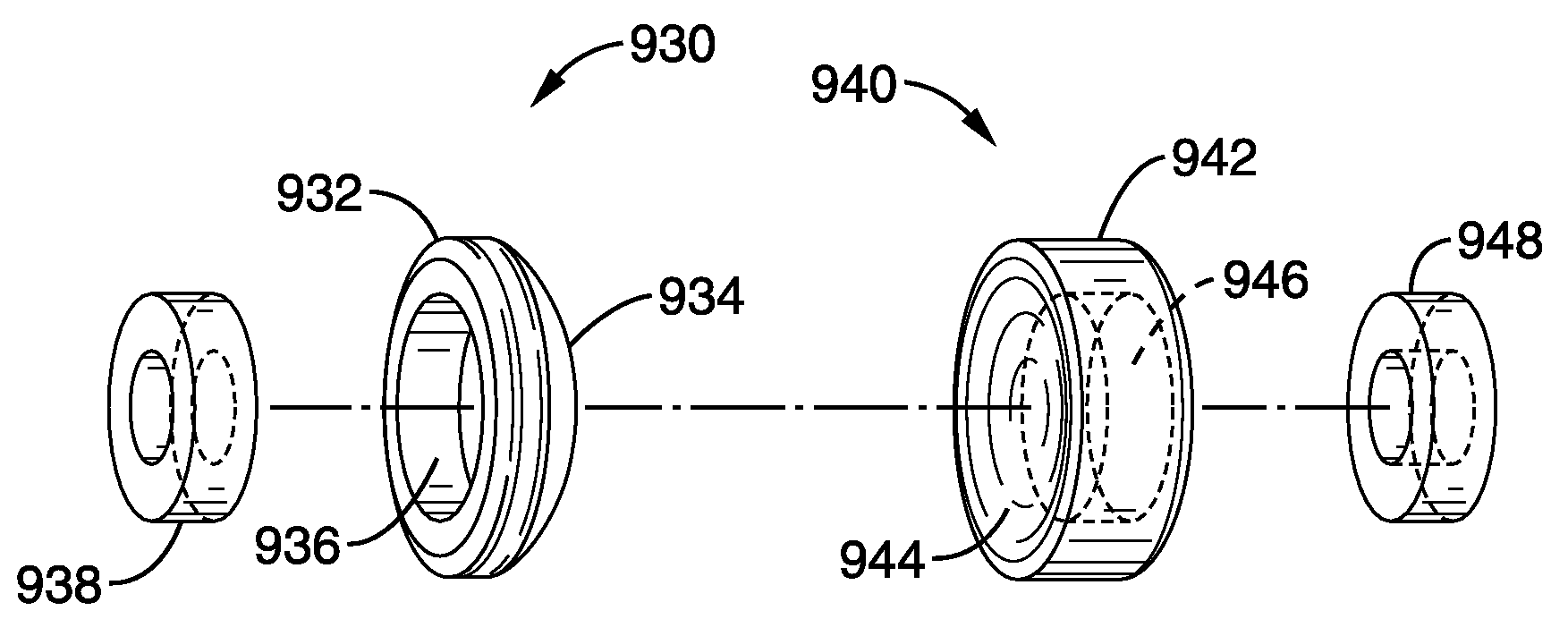
[0229]FIGS. 60-63 illustrate a 3-piece auto-anastomosis system 750 in accordance with the present invention. The system 750 comprises a first magnetic member 732, a second magnetic member 734, and cylindrical cutting member 736 slideably coupled to first magnetic member 732. As shown in FIGS. 62 and 63, the magnetic members 732, 734 and cutter 736 have a substantially circular shape. However, an elliptical shape similar to the system 700 of FIGS. 55-58B may also be used.

[0230]Referring to FIGS. 61A and 61B, the magnetic members 732, 734 comprise opposite polarity magnets 744, 746 that are encapsulated or housed in a biocompatible casing.

[0231]Cutting member 736 comprises a tubular blade 740 coupled to U-shaped cap 742 with a plurality of slots 738 that allow the cap to be snugly positioned on the first magnetic member 732. The cap 72 secures in one of a plurality of grooves 756 (see FIG. 62) on the side of the first magnetic member 732.

[0232]When retained in the upper groove, the ca...

experiment # 1

[0244]Experiment #1

[0245]a. Test Setup

[0246]Two-component magnetic compression devices were manufactured from polytetrafluoroethylene stock. One component (magnetic member) was milled to a convex mucosal (active) surface with a one inch radius of curvature. A doughnut-shaped, axially magnetized neodymium-iron-boron magnet was affixed to the anti-mucosal surface. The complementary component was designed with varying concavity: radii of curvature either infinite (similar to the embodiment shown in FIG. 66A) or one inch (similar to the embodiment shown in FIG. 66AFIG. 66C). An identical toroid magnet was snapped on the anti-mucosal surface of this component as well. Separation distance between the two magnets without interposed tissue was 5 mm. The device pair with a flat component is referred to as the ‘gradient’ device due to its non-uniform, wedge-shaped profile at the compression rim (FIG. 66A). The other pair had matching surface curvature and is titled the ‘uniform’ device in ref...


PUM


Abstract

A system for auto-anastomosing a region of the body using magnetic members that may be individually delivered to different locations in the body. The magnetic members have a polar alignment that generates an attractive force to compress tissue in the region between them. The tissue in the region necroses as a result of the compressive force such that tissue surrounding the necrosed tissue heals together to form an anastomosis. A cutting member may be coupled to either the first or second magnetic member to create a temporary opening in the tissue.

Description

CROSS-REFERENCE TO RELATED APPLICATIONS[0001]This application is a continuation-in-part of copending application Ser. No. 11 / 677,700, filed on Feb. 22, 2007, incorporated herein by reference in its entirety, which is a continuation-in-part of copending application Ser. No. 11 / 431,416, filed on May 9, 2006, incorporated herein by reference in its entirety, which is a continuation-in-part of copending application Ser. No. 10 / 954,995, filed on Sep. 29, 2004, incorporated herein by reference in its entirety.STATEMENT REGARDING FEDERALLY SPONSORED RESEARCH OR DEVELOPMENT[0002]Not ApplicableINCORPORATION-BY-REFERENCE OF MATERIAL SUBMITTED ON A COMPACT DISC[0003]Not ApplicableNOTICE OF MATERIAL SUBJECT TO COPYRIGHT PROTECTION[0004]A portion of the material in this patent document is subject to copyright protection under the copyright laws of the United States and of other countries. The owner of the copyright rights has no objection to the facsimile reproduction by anyone of the patent doc...

Claims


Application Information

Patent Timeline
Patent Type & Authority Applications(United States)
IPC IPC(8): A61B17/11
CPCA61B17/0482A61B17/0483A61B17/1114A61B17/32053A61B17/66A61B17/70A61B2017/1789A61B2017/00411A61B2017/00535A61B2017/00876A61B2017/1139A61B2019/465A61B17/7055A61B17/8076A61B2017/1117A61B2090/065A61B17/1789
Inventor HARRISON, MICHAEL R.FECHTER, RICHARD J.MORAN, ARTHURCHRISTENSEN, DARRELL
Owner RGT UNIV OF CALIFORNIA
Why Eureka
Try Eureka