Spine surgery method and motion preserving implant

a technology of motion preservation and spine surgery, applied in the field of spine surgery, can solve the problems of reducing surgeon reducing the surgeon's visualization of the surgical site, and affecting the operation efficiency of the surgeon, so as to maximize the surface area of boney ingrowth and bone graft-host contact, and enhance the visualization of bone graft-vertebral. the effect of enhancing the visualization

Active Publication Date: 2009-02-19
FABIAN JR HENRY F
View PDF0 Cites 77 Cited by
  • Summary
  • Abstract
  • Description
  • Claims
  • Application Information

AI Technical Summary

Benefits of technology

[0029]One advantage of this invention is that the implant has an open profile when fully expanded, maximizing boney ingrowth surface area and bone graft-host contact.
[0030]Another advantage of this invention is that the surgeon achieves enhanced visualization of the bone graft-vertebral body endplate interface.
[0031]Another advantage of this invention is that the implant allows for minimally invasive deployment via either an anterior, posterior or anterolateral surgical approach.

Problems solved by technology

As a result, known spinal surgical methods, instrumentation and interbody implants have disadvantages.
One disadvantage is that the physical components are relatively large and bulky.
This reduces surgeon visualization of the surgical site.
Another disadvantage of know spinal surgical methods is that known surgical tools and implants are cumbersome and difficult to maneuver within the limited surgical space available.
Despite this progression in intradiscal implant geometry, a device having an optimized geometry to provide an optimal vertebral endplate footplate is lacking.
A specific surgical method and complementary implant instrumentation system is also lacking.
These known techniques along with their associated instruments and implants lack one or more of the criteria for optimal use in anterior, posterior, or transforaminal minimally invasive approaches compatible with currently available minimally invasive spine surgery and / or minimal access spinal techniques (MAST).

Method used


Image

  • Spine surgery method and motion preserving implant
  • Spine surgery method and motion preserving implant
  • Spine surgery method and motion preserving implant

Examples


Embodiment Construction

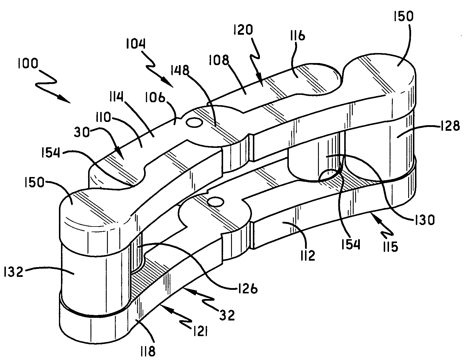
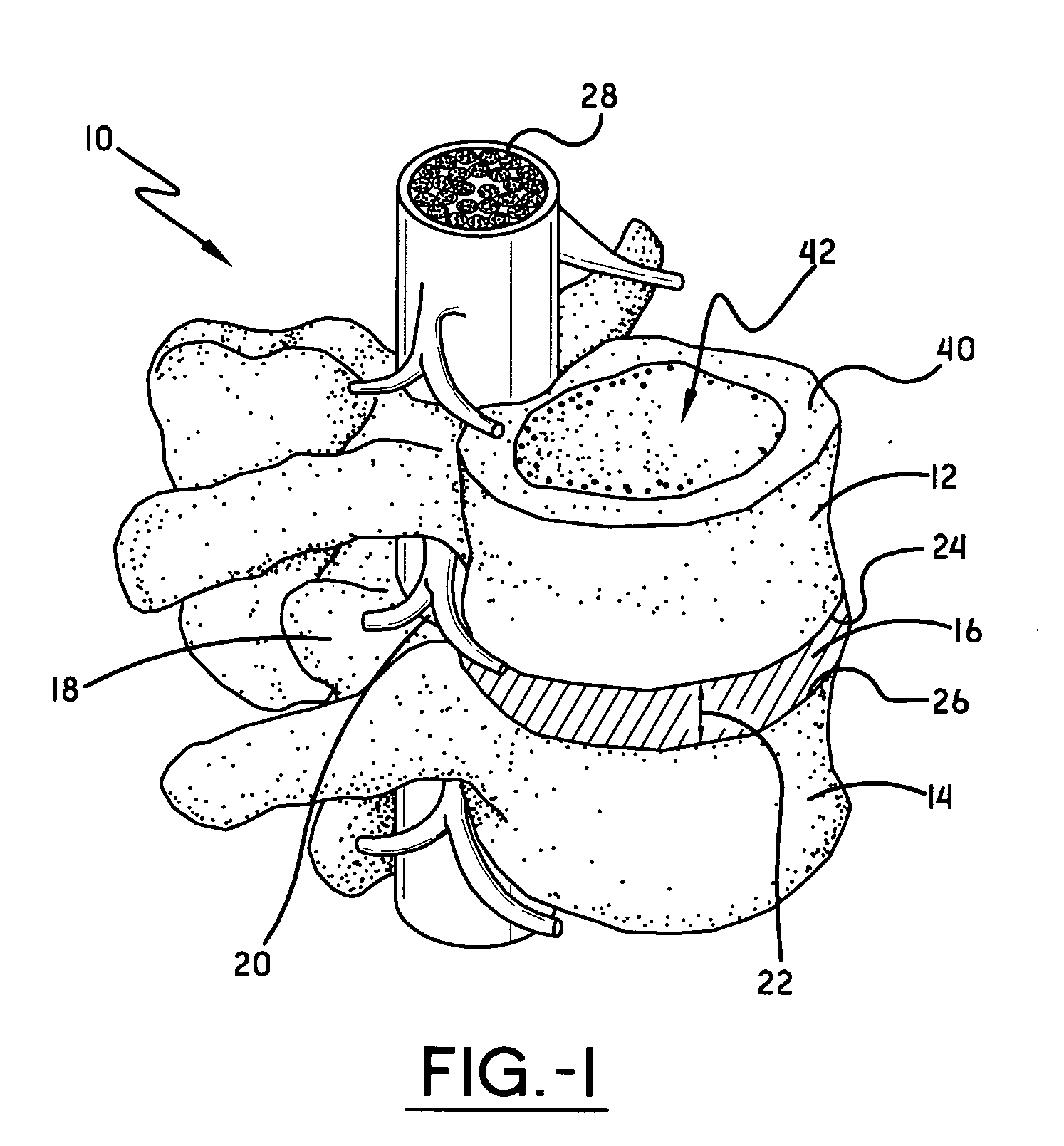
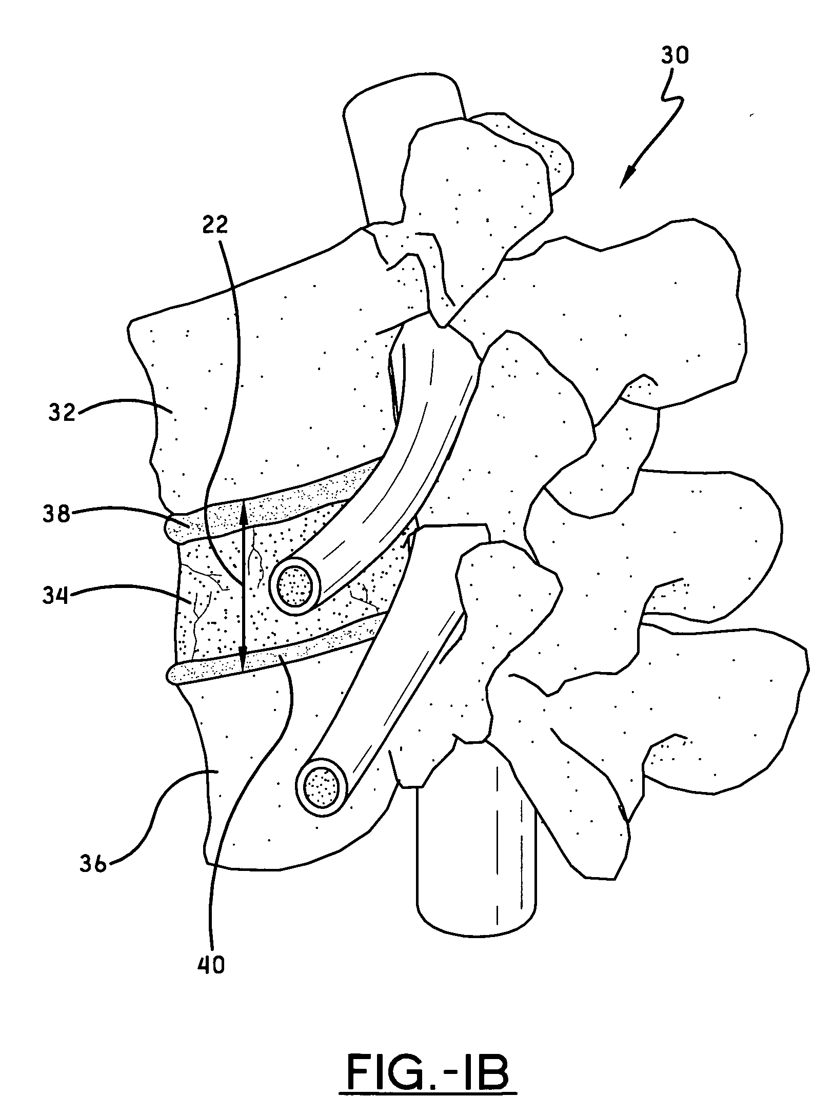
[0071]Referring now to the drawings wherein the showings are for purposes of illustrating embodiments of the invention only and not for purposes of limiting the same, the implants of this invention may be inserted within and, in some embodiments deployed within a vertebral space 22. By vertebral space it is meant the space in a spinal column where the implant 100 will be placed. In one embodiment, shown in FIG. 1A, a spinal segment 10 is made up of two vertebrae 12, 14 attached together by ligaments with a disc 16 separating them. Facet joints 18 fit between the two vertebrae 12, 14 and allow for movement. The neural foramen 20 between the vertebrae 12, 14 allow space for the nerve roots to travel freely from the spinal cord 28 to the body. If it is required to remove the disc 16 and replaced it with an implant 100, the space occupied by the disc 16, the intradiscal space between the two adjacent vertebral bodies 12, 14, defines the vertebral space 22. In another embodiment, shown i...


PUM

PropertyMeasurementUnit
lengthaaaaaaaaaa
viscoelasticaaaaaaaaaa
length variableaaaaaaaaaa

Abstract

A spinal implant may be deployable, when positioned within a vertebral space between a pair of vertebral bodies, from a first laterally non-expanded condition to a second laterally expanded condition. The spinal implant may include top beams and bottom beams separated by at least one post that is, in one embodiment, length variable in response to a load put on the implant after deployment of the implant. In an alternate embodiment, at least one post is laterally variable in response to a load put on the implant. In another embodiment, one of the posts may be centrally located.

Description

[0001]This application is a Continuation-In-Part claiming priority from U.S. Ser. No. 11 / 236,068, entitled SPINE SURGERY METHOD AND IMPLANT, filed Sep. 27, 2005, which is incorporated herein by reference.I. BACKGROUND OF THE INVENTION[0002]A. Field of Invention[0003]This invention pertains to the art of methods and apparatuses regarding spine surgery and more specifically relates to surgical procedures, associated instrumentation and a motion preserving implant to be positioned within, and in some embodiments deployed within, a vertebral space.[0004]B. Description of the Related Art[0005]The volume of spinal surgeries to treat degenerative disc and facet disease has steadily increased over the past decade, fueled by population demographics and advancements in diagnostic and instrumentation adjuncts. Improvements in intraoperative radiological imaging and surgical technique have generated a great deal of interest in applying minimally invasive surgical (MIS) techniques to spinal appl...

Claims


Application Information

Patent Timeline
Patent Type & Authority Applications(United States)
IPC IPC(8): A61F2/44
CPCA61F2/30744A61F2310/00179A61F2/441A61F2/442A61F2/4455A61F2/4684A61F2002/2835A61F2002/30014A61F2002/30179A61F2002/30462A61F2002/30471A61F2002/30492A61F2002/30505A61F2002/30561A61F2002/30563A61F2002/30568A61F2002/30579A61F2002/30601A61F2002/30616A61F2002/30836A61F2002/30841A61F2002/30904A61F2002/4415A61F2002/4619A61F2220/0025A61F2220/0075A61F2220/0091A61F2230/0058A61F2250/0018A61F2310/00017A61F2310/00023A61F2310/00029A61F2/30965
Inventor FABIAN, JR., HENRY F.
Owner FABIAN JR HENRY F
Why Eureka
Try Eureka