Wide-angle lenses

Inactive Publication Date: 2009-02-26
NANOPHOTONICS CO LTD
View PDF7 Cites 19 Cited by
  • Summary
  • Abstract
  • Description
  • Claims
  • Application Information

AI Technical Summary

Benefits of technology

[0075]By providing new projection schemes explicitly reflecting the field of view and the imag

Problems solved by technology

Therefore, it is not legitimate to apply these concepts to an ultra wide-angle lens where the maximum incidence angle is relatively large.
However, even in such a case, the assumption of Equation 2 is no more than an approximate relation satisfied within the limit of paraxial ray tracing and it is not a mathematically exact equation.
In addition, since the modern advanced optical lens has many lens elements and the field of view is getting ever wider, the assumption of paraxial ray tracing is no more valid.
For such a reason, a lens satisfying the first type of projection scheme and a lens satisfying the second type of projection scheme are substantially different from each other, and especially, designing the two types of lenses result

Method used


Image

  • Wide-angle lenses
  • Wide-angle lenses
  • Wide-angle lenses

Examples


first embodiment

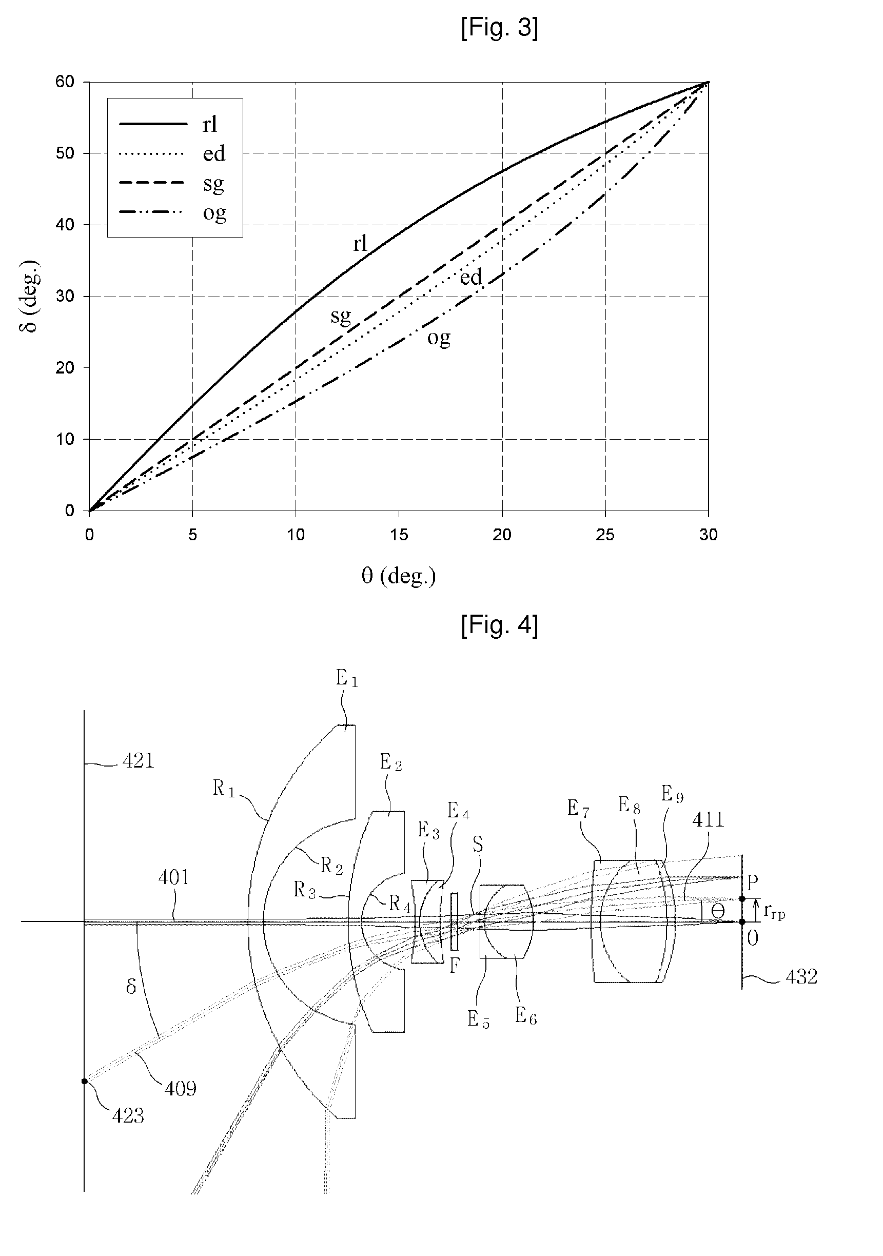
[0172]FIG. 30 shows the optical layout and the ray traces of a rotationally symmetric refractive rectilinear wide-angle lens according to the first embodiment of the present invention satisfying the rectilinear projection scheme given by Equation 36. This lens is designed to operate in the visible wavelength range, F number is 2.8, the field of view is 120° (i.e., δ2=60°), and optimized for a VGA-grade ⅓-inch CCD image sensor. A ⅓-inch CCD sensor has a width of 4.8 mm (i.e., W=4.8 mm), a height of 3.6 mm (i.e., H=3.6 mm), and a diagonal dimension of 6.0 mm. Accordingly, the maximum image height is r2=3.0 mm in order to prevent the vignetting effect.

[0173]This lens includes a first lens element E through an eleventh lens element E11 wherein the first lens element E1 is a double aspheric lens element, while the rest of the elements from the second element E1 to the eleventh lens element E11 are all spherical refractive lens elements. The stop S is located between the third lens elemen...

second embodiment

[0191]FIG. 40 is the optical layout and ray traces of a refractive rectilinear wide-angle lens with a CS mount according to the second embodiment of the present invention. Similar to the first embodiment, the field of view is 120°, and the F number is 4.4. This lens differs from the lens in the first embodiment in that the back focal length is longer than 12.5 mm. In this lens, the first lens element E1 is also a double aspheric lens element having a first lens surface R1 which is described by a polynomial and a second lens surface R2 which is described by an even aspheric lens formula. In addition, each of the second lens element E2 through the eleventh lens element E11 is a spherical lens element, and the stop S is located between the third lens element E3 and the fourth lens element E4. Table 4 summarizes the profile of the first lens surface R1, Table 5 summarizes the profile of the second lens surface R2 and Table 6 summarizes the lens design data for the entire lens except for...

third embodiment

[0193]FIG. 44 is the optical layout and the ray traces of a rectilinear wide-angle lens according to the third embodiment of the present invention. The field of view of this lens is 125° and the F number is 3.92. In this lens, the first lens element E1 is also a double aspheric lens element having a first lens surface R1 which is described by a polynomial and a second lens surface R2 which is described by an even aspheric lens formula, and all the other lens elements are spherical lens elements. A stop S is located between the fourth lens element E4 and the fifth lens element E5, and the optical low pass filter F is located between the twelfth lens element E12 and the image plane 4432. Table 7 summarizes the aspherical surface profile of the first lens surface R1 Table 8 summarizes the aspherical surface profile of the second lens surface R2 and Table 9 summarizes the entire lens design data except for the two aspherical surface profiles. All the spherical lens elements are selected...


PUM


Abstract

The present invention provides new projection schemes for wide angle imaging lenses rotationally symmetric about optical axis wherein the field of view of lenses and the size of image sensors are directly reflected without any reference to the effective focal length of the lenses. This invention also provides explicit examples of wide-angle lenses implementing the newly developed projection schemes. According to the present invention, by providing new projection schemes explicitly reflecting the physical quantities of direct interest to the user for industrial applicability, namely, the field of view and the image sensor size, it is possible to realize wide-angle lenses providing the most satisfactory images.

Description

TECHNICAL FIELD[0001]The present invention relates to a lens having a specific projection scheme, and more specifically, an object of the present invention is to provide an imaging lens having at least one lens element and a stop and implements a specific projection scheme so that the imaging lens provides a superb image most satisfying for the particular application purpose of the image acquisition.BACKGROUND ART[0002]FIG. 1 is a schematic diagram illustrating the relationship between the incidence angle δ of an incident ray 109 and the exit angle θ of an exit ray 111 in accordance with a projection scheme which is useful in an imaging optical system such as a camera. The camera comprises a lens 110 and a camera body 112 having an image sensor therein. The lens 110 is assumed to be rotationally symmetric about an optical axis 101. In an ideal camera model, the lens is considered as a pinhole. The nodal point N of the lens is the point corresponding to the position of the pinhole. T...

Claims


Application Information

Patent Timeline
IPC IPC(8): G02B13/08
CPCG02B13/06G02B17/08G02B13/08G02B13/003G02B13/18G03B9/02
Inventor KWEON, GYEONG IILAIKIN, MILTON
Owner NANOPHOTONICS CO LTD
Why Eureka
Try Eureka