Optical pick-up

a pickup and optical technology, applied in the field of optical pickups, can solve the problems of not being able to achieve information recording or information reproducing, and achieve the effects of increasing the cost of coupling lenses, and increasing the number of components

Inactive Publication Date: 2009-02-26
HOYA CORP
View PDF13 Cites 6 Cited by
  • Summary
  • Abstract
  • Description
  • Claims
  • Application Information

AI Technical Summary

Benefits of technology

[0006]Although the optical pick-up disclosed in JP 2004-247025A is able to achieve information recording or information reproducing for an optical disc having a higher recording density than DVD, the optical pick-up needs to employ a dedicated optical element for correction of aberrations or to form a diffraction structure on the coupling lens, in addition to forming a diffraction structure on the objective lens. Such a configuration increases the number of components in the optical pick-up.
[0007]The present invention is advantageous in that it provides an optical pick-up capable of recording information to and / or reproducing information from a plurality of types of optical discs including a CD, a DVD and an optical disc having a higher recording density than DVD, without increasing the number of components and expense of a coupling lens, while suppressing aberrations due to temperature variations.
[0010]With this configuration, it is possible to achieve a high use efficiency of light for each of the first, second and third light beams. Such a configuration makes it possible to use the second order diffraction light for the first light beam and the first order diffraction light for each of the second and third light beams. Therefore, by appropriately setting the magnification for each of the first to third optical discs, the spherical aberration can be suppressed for each of the first to third light beams. In particular, by causing a converging beam to enter the objective lens when the first optical disc having the highest recording density is used, it is possible to suppress the spherical aberration due to temperature variations to a low level. Consequently, it is possible to provide an optical pick-up capable of recording information to and / or reproducing information from a plurality of types of optical discs including a CD, a DVD and an optical disc having a higher recording density than DVD, without increasing the number of components and expense of a coupling lens, while suppressing aberrations due to temperature variations.
[0028]With this configuration, it is possible to achieve a high use efficiency of light for each of the first, second and third light beams. Such a configuration makes it possible to user the second order diffraction light for the first light beam and the first order diffraction light for each of the second and third light beams. Therefore, by appropriately setting the magnification for each of the first to third optical discs, the spherical aberration can be suppressed for each of the first to third light beams. In particular, by causing a converging beam to enter the objective lens when the first optical disc having the highest recording density is used, it is possible to suppress the spherical aberration due to temperature variations to a low level. Consequently, it is possible to provide an optical pick-up capable of recording information to and / or reproducing information from a plurality of types of optical discs including a CD, a DVD and an optical disc having a higher recording density than DVD, without increasing the number of components and expense of a coupling lens, while suppressing aberrations due to temperature variations.

Problems solved by technology

However, the optical pick-up disclosed in JP HEI 9-306024A is configured to achieve information recording or information reproducing only for the two types of optical discs (i.e., DVD and CD), and is not configured to achieve the information recording or information reproducing for three types of optical discs including an optical disc (e.g., HD DVD) having a higher recording density than DVD.

Method used


Image

  • Optical pick-up
  • Optical pick-up
  • Optical pick-up

Examples


first embodiment

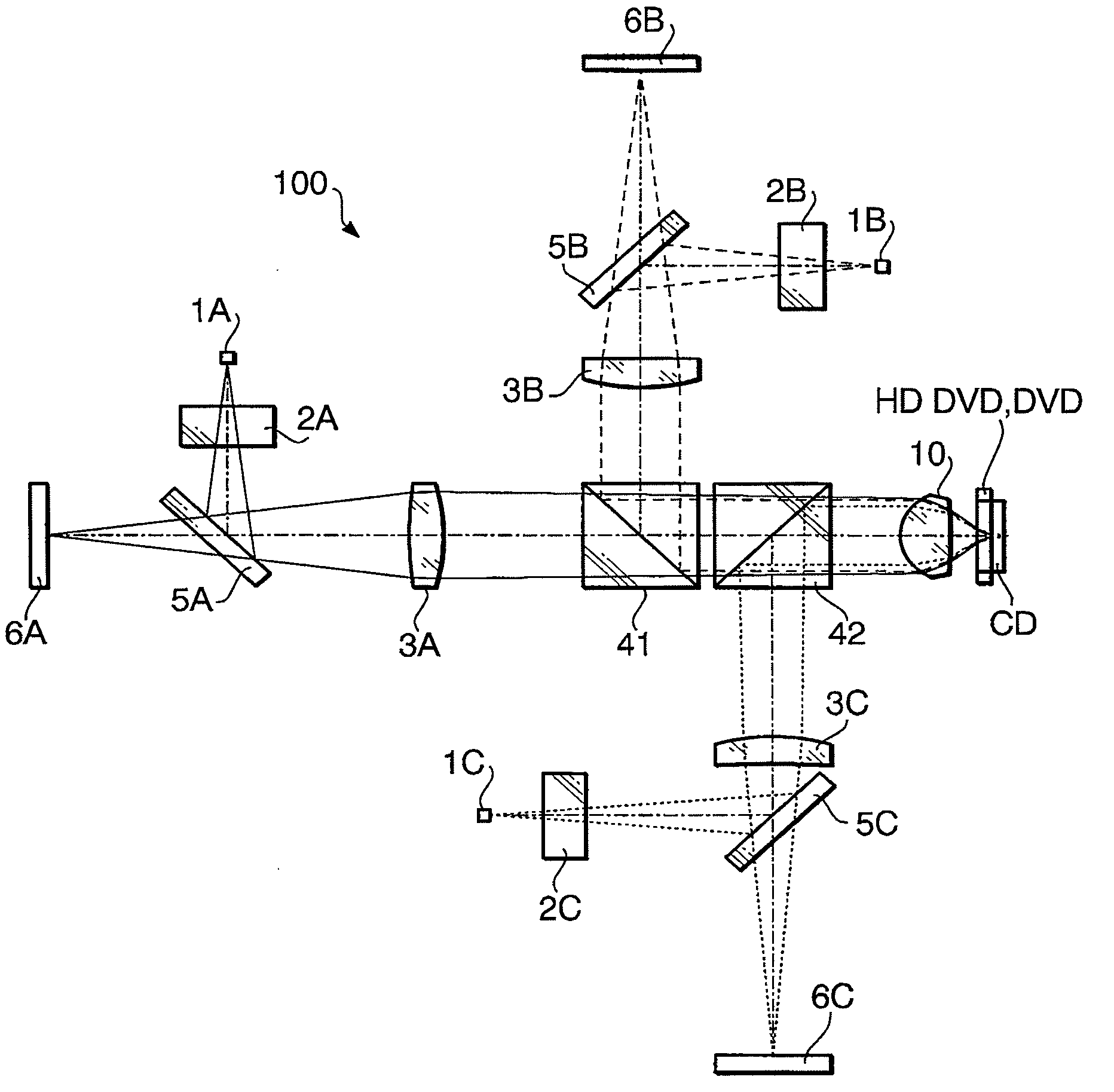
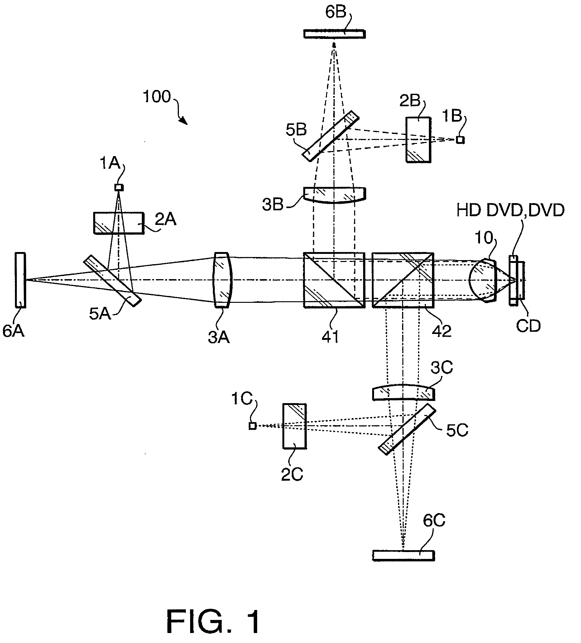
[0052]Hereafter, an optical pick-up according to a first embodiment is explained. The optical pick-up is used for recording information to and / or reproducing information from a plurality of types of optical discs including a first optical disc (e.g., HD DVD) having the highest recording density and having the protective layer thickness of 0.6 mm, a second optical disc (e.g., DVD) having the second highest recording density and having the protective layer thickness of 0.6 mm and a third optical disc (e.g., CD) having the lowest recording density and having the protective layer thickness of 1.2 mm.

[0053]In the following, the term “compatibility” means that the optical pick-up ensures the information reproducing and / or information recording with no need of component replacement even when the optical disc being used is switched.

[0054]FIG. 1 is an exemplary example of a block diagram of an optical system in an optical pick-up 100 according to the first embodiment. FIG. 2A illustrates a d...

second embodiment

[0093]Hereafter, an optical pick-up according to a second embodiment is explained. Since the optical pick-up according to the second embodiment has substantially the same optical block diagram as that of the first embodiment, the following explanation of the second embodiment focuses on the feature of the second embodiment.

[0094]The following Table 12 shows concrete specifications of a second embodiment of the optical pick-up 100. The optical block diagram of the optical pick-up 100 according to the second embodiment is shown in FIG. 1. The developed optical block diagram defined when the first optical disc is used is shown in FIG. 5A. The developed optical block diagram defined when the second optical disc is used is shown in FIG. 5B. The developed optical block diagram defined when the third optical disc is used is shown in FIG. 5C.

TABLE 121st laser2nd laser3rd laserbeambeambeamWavelength (nm)405660790Focal Length (mm)3.003.123.12NA0.650.600.47Magnification M0.0300.000−0.041

[0095]...

third embodiment

[0108]Hereafter, an optical pick-up according to a third embodiment is explained. Since the optical pick-up according to the third embodiment has substantially the same optical block diagram as that of the first embodiment, the following explanation of the third embodiment focuses on the feature of the third embodiment.

[0109]The following Table 22 shows concrete specifications of a third embodiment of the optical pick-up 100. The optical block diagram of the optical pick-up 100 according to the third embodiment is shown in FIG. 1. The developed optical block diagram defined when the first optical disc is used is shown in FIG. 8A. The developed optical block diagram defined when the second optical disc is used is shown in FIG. 8B. The developed optical block diagram defined when the third optical disc is used is shown in FIG. 8C.

TABLE 221st laser2nd laser3rd laserBeamBeamBeamWavelength (nm)405660790Focal Length (mm)2.302.372.39NA0.660.600.47Magnification M0.0350.000−0.050

[0110]Table ...


PUM

PropertyMeasurementUnit
thickness t3aaaaaaaaaa
wavelengthaaaaaaaaaa

Abstract

There is provided an optical pick-up including first to third light sources respectively emitting first to third light beams, a first coupling lens, and an objective lens formed to converge each of the first, second and third light beams onto the first, second and third optical discs, respectively. The objective lens has a step structure including a plurality of concentrically formed refractive surface zones divided by steps, the step structure having a function of giving, at each step, an optical path length difference of approximately 2λ1 to the first light beam. The first coupling lens causes the first light beam to be incident on the objective lens as a converging beam. The objective lens is positioned to satisfy a condition:−0.35<f2×M2−f1×M1<−0.07  (1).

Description

BACKGROUND OF THE INVENTION[0001]The present invention relates to an optical pick-up used for recording information to and / or reproducing information from three types of optical discs of different standards including CD, DVD and a high recording density optical disc (e.g., HD DVD or BD).[0002]An optical pick-up configured to use a common objective lens for all of a plurality of types of optical discs of different standards has become widespread. Japanese Patent Provisional Publication No. HEI 9-306024 (hereafter, referred to as JP HEI 9-306024A) discloses an optical pick-up employing a common objective lens used for CD and DVD. The optical pick-up disclosed in JP HEI 9-306024A is configured to change magnification of the objective lens in accordance with the type of the optical disc being used to suppress aberrations caused by temperature variations. More specifically, in the optical pick-up, a converging light beam is incident on the objective lens when DVD is used, while a substan...

Claims


Application Information

Patent Timeline
Patent Type & Authority Applications(United States)
IPC IPC(8): G11B7/135
CPCG11B7/1353G11B7/1374G11B2007/0006G11B7/13922G11B7/1376
Inventor KOREEDA, DAISUKETAKEUCHI, SHUICHI
Owner HOYA CORP
Why Eureka
Try Eureka