
Apparatus and method for signaling in a wireless communication system

a wireless communication system and apparatus technology, applied in the field of apparatus and methods for signaling communications in a packet data network, can solve the problems of inability to pass, inefficient scenario, waste of valuable resources, and current techniques that are suboptimal, and achieve the effect of reducing one or two, alleviating one or two, and reducing the number o

Active Publication Date: 2009-02-26
SONY CORP
View PDF87 Cites 87 Cited by
  • Summary
  • Abstract
  • Description
  • Claims
  • Application Information

AI Technical Summary

Benefits of technology

[0024]In this manner, a mechanism to police the AMBR value in the Node-B without wasting unnecessarily uplink resource is provided by modifying, for example, the scheduler function in the Node-B to assign scheduling parameters relevant to the value of the UL AMBR that has to be enforced for radio bearers serving on UE-PDN connection.
[0025]Thus, embodiments of the invention may allow improved use of the communication resource by more efficiently utilizing uplink resources in the communication system, for example, as a result of not admitting by the Node-B uplink (UL) traffic transmitted by the UE that may have to be dropped later if it exceeded the AMBR value.
[0026]Consequently, the invention may provide increased throughput rates and increase the capacity in the communication system by not admitting traffic that may have to be subsequently dropped. Furthermore, the invention may allow improved performance, as perceived by the end-users, and also may allow the network operator to increase a number of users that can be supported by the system, whilst still being able to control the UL AMBR that is transmitted by the UEs to a certain PDN connection.

Problems solved by technology

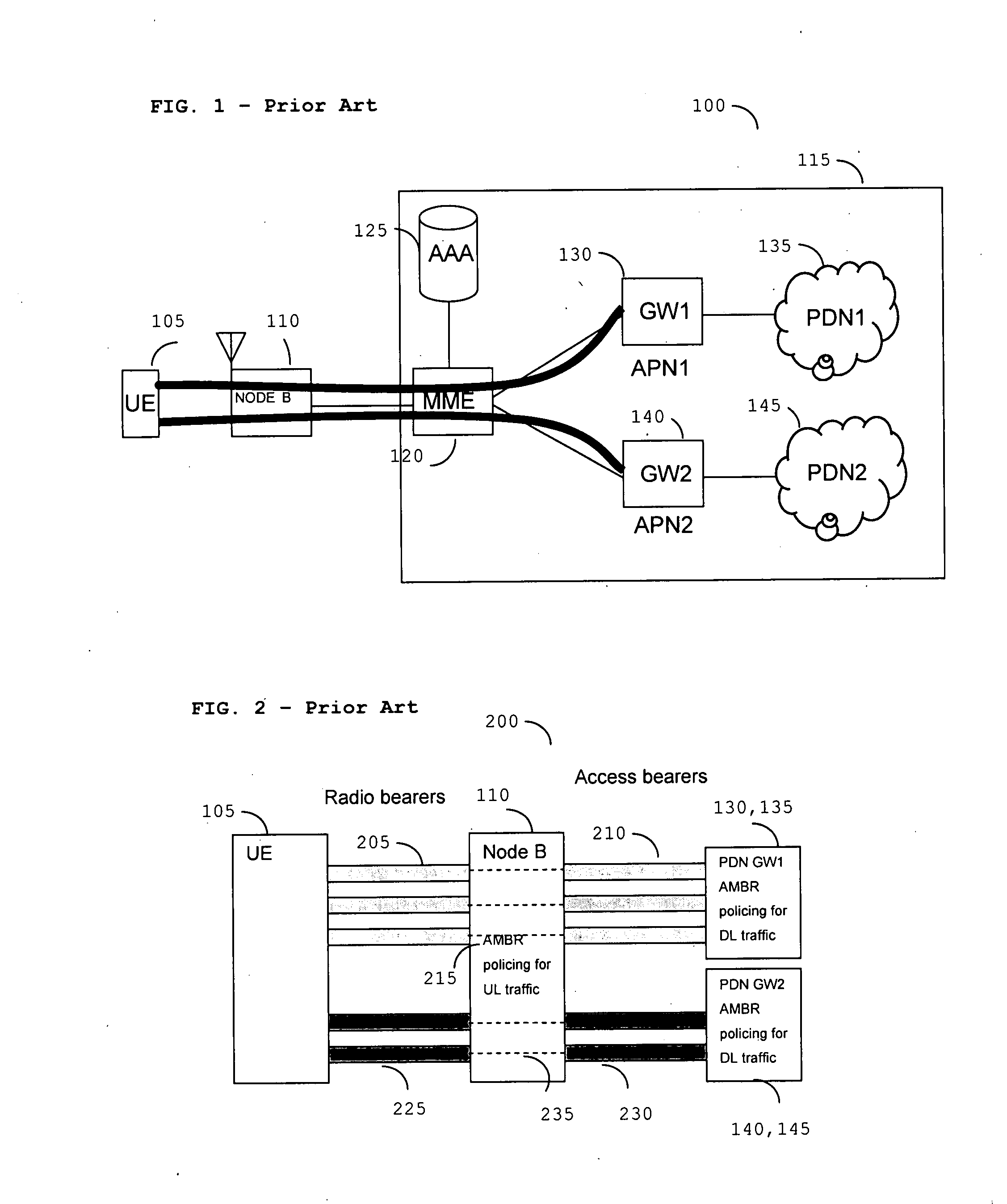
Furthermore, as radio resources are the most cost sensitive for a wireless Operator, it is not reasonable to ‘pass through’ UL traffic over an air-interface when the UL traffic will be later discarded.
Thus, this scenario is inefficient and wasteful of valuable resource.
Consequently, current techniques are suboptimal.

Method used


Image

  • Apparatus and method for signaling in a wireless communication system
  • Apparatus and method for signaling in a wireless communication system
  • Apparatus and method for signaling in a wireless communication system

Examples


Embodiment Construction

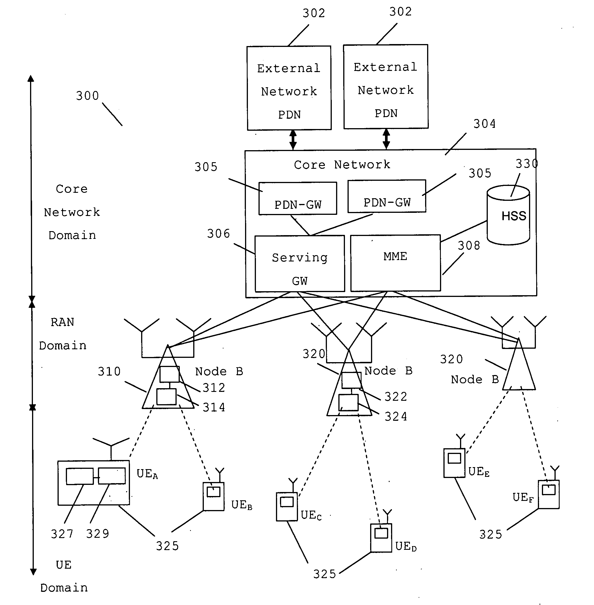
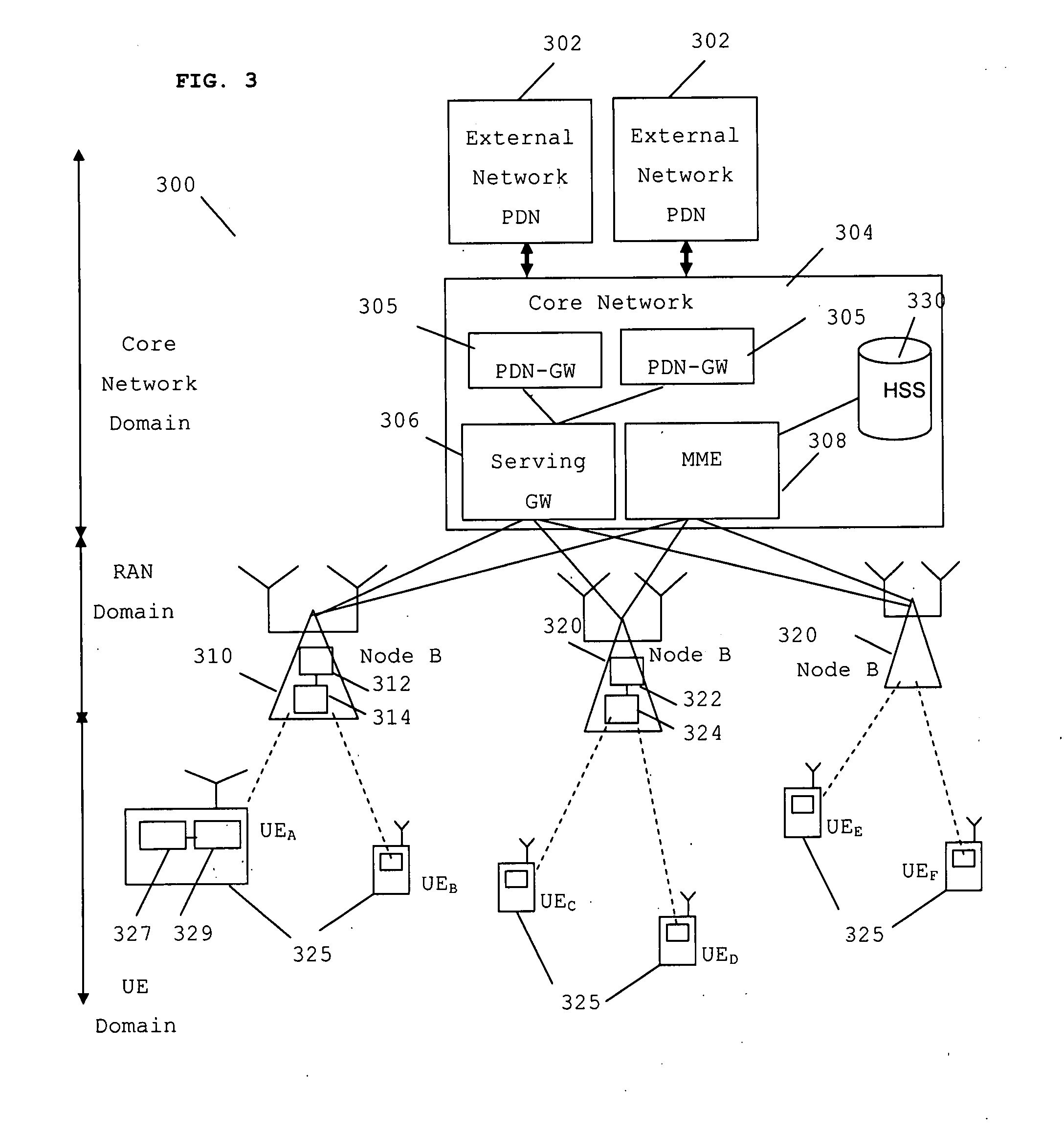
[0056]The following description focuses on embodiments of the invention applicable to a Evolved-UMTS (Universal Mobile Telecommunication System) cellular communication system and in particular to a Evolved Packet System (EPS) core network (CN) architecture within a 3rd generation partnership project (3GPP) system. However, it will be appreciated that the invention is not limited to this particular cellular communication system, but may be applied to other cellular communication systems.

[0057]Embodiments of the invention propose to obtain the AMBR parameter with its associated PDN connection identifier from a static subscriber database when the communication endpoint bootstraps and attaches initially in the network. Furthermore, and advantageously, the AMBR is communicated with its associated PDN connection identifier to the network element that is responsible to police and enforce the AMBR per PDN connection.

[0058]In addition, some embodiments propose a network element enforcing the...


PUM


Abstract

A method of signaling in a wireless communication system (300) comprising a first network element (310) serving a wireless communication unit (325) with at least one packet data network (PDN) connection. The method comprises transmitting, by the first network element (310) to the wireless communication unit (325), a signaling message relating to a wireless communication unit (325) uplink (UL) PDN transmission, where the signaling message comprises a parameter indicative of at least one aggregate maximum bit rate (AMBR) value.

Description

FIELD OF THE INVENTION[0001]The invention relates to apparatus and methods for signaling communications in a packet data network, such as a 3rd Generation Partnership Project (3GPP) cellular communication system.BACKGROUND OF THE INVENTION[0002]Currently, 3rd generation cellular communication systems are being rolled out to further enhance the communication services provided to mobile phone users. The most widely adopted 3rd generation communication systems are based on Code Division Multiple Access (CDMA) and Frequency Division Duplex (FDD) or Time Division Duplex (TDD) technology. Further description of CDMA, and specifically of the Wideband CDMA (WCDMA) mode of UMTS, can be found in ‘WCDMA for UMTS’, Harri Holma (editor), Antti Toskala (Editor), Wiley & Sons, 2001, ISBN 0471486876.[0003]In 3GPP systems, such as the General Packet Radio System (GPRS), Evolved Packet System (EPS), the downlink communication endpoint, namely the mobile or handheld wireless communication unit, referr...

Claims


Application Information

Patent Timeline
IPC IPC(8): H04Q7/00G08C15/00H04Q7/20H04Q7/24
CPCH04L47/14H04L47/263H04W28/12H04W28/22H04W72/1242H04W72/1278H04L5/0064H04W76/025H04W72/042H04W72/10H04W36/0033H04W72/1236H04W72/08H04W76/15H04W28/0268H04W72/569H04W72/20H04L1/0002H04W72/04H04W72/12H04L5/0053H04L5/0091H04W8/04H04W72/54H04W72/56H04W72/543H04W72/23
Inventor ZISIMOPOULOUS, HARISWORRAL, CHANDRIKA K.
Owner SONY CORP
Learn More