
Optical pickup and optical disc device

a pickup and optical disc technology, applied in the direction of optical beam sources, instruments, semiconductor lasers, etc., can solve the problems of laser light intensity fluctuations, achieve the effect of effectively suppressing the waveform of driving signal deterioration, shortening the aforementioned transmission line, and efficiently connecting the integrated circuit elemen

Inactive Publication Date: 2009-02-26
PANASONIC CORP
View PDF7 Cites 6 Cited by
  • Summary
  • Abstract
  • Description
  • Claims
  • Application Information

AI Technical Summary

Benefits of technology

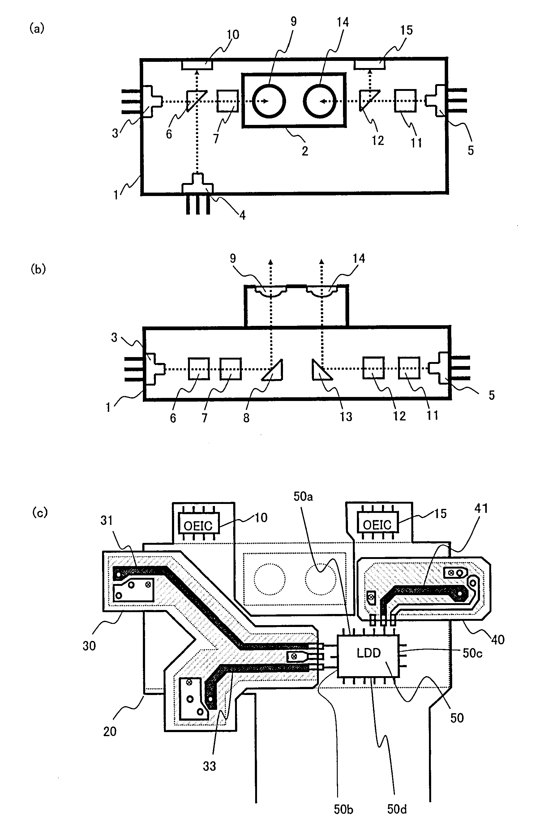
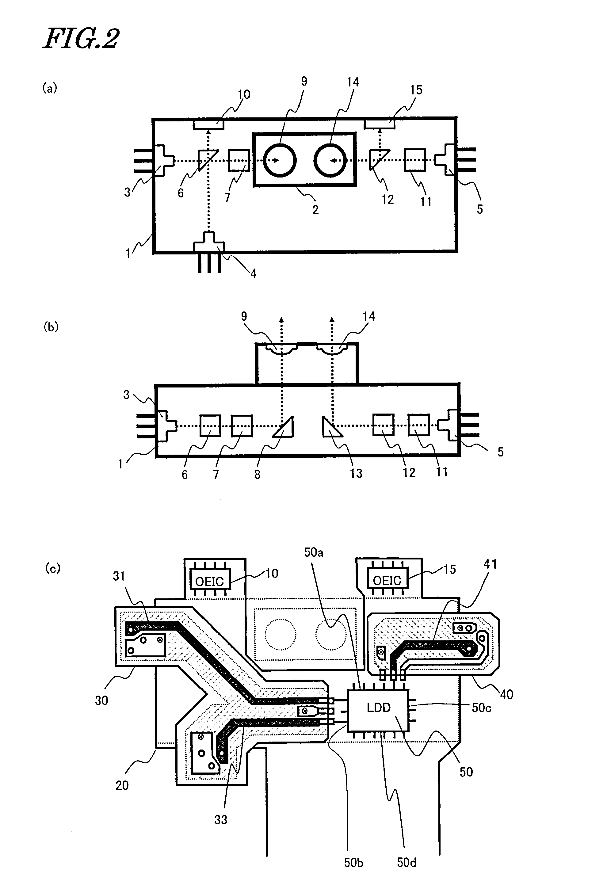
[0020]In an optical pickup according to the present invention, an integrated circuit element for driving three types of semiconductor lasers is placed in an appropriate position within the optical pickup, such that the length of a transmission line for connecting a semiconductor laser which emits a light beam of the shortest wavelength (short-wavelength laser) to the integrated circuit element is shorter than transmission lines for connecting the other semiconductor lasers to the integrated circuit element. Since the short-wavelength laser is modulated with the highest speed, deteriorations in the signal waveform are likely to occur in the process during which a driving signal is propagated through the transmission line, but according to the present invention, the shortened transmission line effectively suppresses deteriorations in the waveform of the driving signal.
[0021]Moreover, according to the present invention, in order to shorten the aforementioned transmission line, a novel construction is adopted for the connections between the integrated circuit element for laser driving and the semiconductor lasers. Specifically, a construction is adopted where, of the four sides of a rectangular principal face of the integrated circuit element, a side along which pins to be connected to the short-wavelength laser are provided is orthogonal to the sides along which pins to be connected to the other semiconductor lasers are provided. As a result, while efficiently connecting the integrated circuit element to the three semiconductor lasers, it also becomes possible to efficiently connect the integrated circuit element to circuits (signal processing circuitry and control circuitry) provided externally to the optical pickup. Thus, wasteful space is reduced and the optical pickup can be downsized.

Problems solved by technology

If a portion of the laser light that has been reflected from the optical disk enters the semiconductor laser, the oscillation state of the laser is disturbed, thus resulting in problematic fluctuations of the intensity of laser light.

Method used


Image

  • Optical pickup and optical disc device
  • Optical pickup and optical disc device
  • Optical pickup and optical disc device

Examples


embodiment 1

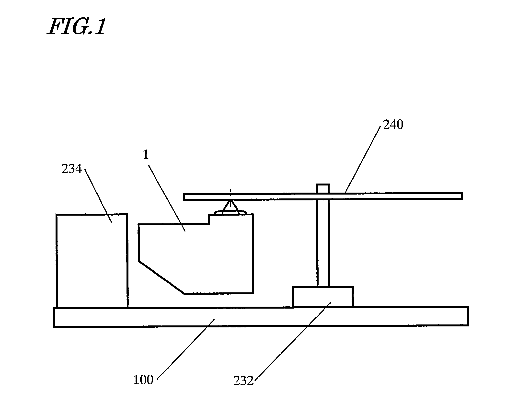
[0051]Hereinafter, a first embodiment of the optical disk apparatus according to the present invention will be described with reference to the figures.

[0052]First, FIG. 1 is referred to. FIG. 1 is a diagram showing the construction of a main portion of the optical disk apparatus of the present embodiment. This optical disk apparatus includes: a spindle motor 232 which rotates an optical disk 240; and an optical pickup 1 for performing data recording / reproduction for the optical disk 240. The internal construction of the optical pickup 1 will be specifically described later.

[0053]The optical pickup 1 is supported by a stepping motor or DC motor (not shown) so as to be movable. Thus, the optical pickup 1 is able to perform a traverse operation along a radial direction of the optical disk 240. With this traverse operation, the optical pickup 1 is able to access a target track on the optical disk 240. In order to realize a rapid traverse operation, it is preferable that the optical pick...

embodiment 2

[0108]Next, a second embodiment of the optical disk apparatus according to the present invention will be described with reference to FIG. 10. FIG. 10 is a construction diagram showing an optical pickup according to the present embodiment.

[0109]The optical pickup of the present embodiment includes three semiconductor lasers 201, 202, and 203 having different oscillation wavelengths, but differs from the optical pickup of Embodiment 1 in that there is only a single objective lens 227 that converges a light beam onto an optical disk 240.

[0110]The optical pickup of the present embodiment includes a flexible printed wiring board 212 on which a laser driving IC 204 and a photodetector 209 as well as other electrical parts (not shown) are mounted. On the flexible printed wiring board 212, wiring lines 205, 206, and 207 are formed from a copper foil pattern. The wiring lines 205, 206, and 207 constitute transmission lines for connecting the semiconductor lasers 201, 202, and 203, respective...


PUM

PropertyMeasurementUnit
wavelengthaaaaaaaaaa
lengthsaaaaaaaaaa
lengthsaaaaaaaaaa

Abstract

An optical pickup according to the present invention includes an integrated circuit element (LDD) 5 for driving first, second, and third semiconductor lasers 3, 4, and 5. The LDD 50 is shaped so as to have a rectangular principal face surrounded by one side, with a plurality of input / output pins being arranged along each side. The plurality of input / output pins include a first pin group connected to a blue-violet laser 5 whose oscillation wavelength is the shortest, a second pin group connected to a red laser 4, and a third pin group connected to an infrared laser 3. The wiring structure of the optical pickup includes a first transmission line 41 for connecting the first pin group to the blue-violet laser 5, a second transmission line 33 for connecting the second pin group to the red laser 4, and a third transmission line 31 for connecting the third pin group to the infrared laser 3, where the first transmission line 41 is shorter than both the second and third transmission lines 31 and 33. Of the rectangular principal face of the LDD 50, the side along which the first pin group is provided is orthogonal to the side along which the second pin group is provided or to the side along which the third pin group is provided.

Description

TECHNICAL FIELD[0001]The present invention relates to an optical pickup, and an optical disk apparatus having the optical pickup.BACKGROUND ART[0002]In a recording / reproduction apparatus for optical disks, in order to read data from an optical disk or write data to an optical disk, it is necessary to access a desired position on the optical disk with an optical pickup. An optical pickup includes: a light source for emitting a light beam; an objective lens for converging the light beam onto an optical disk; and photosensitive elements for outputting electrical signals based on the light beam having been reflected from the optical disk.[0003]A semiconductor laser is used as a light source in within the optical pickup. The semiconductor laser operates with a driving current which is supplied from the laser driving circuit, and is able to emit laser light at an intensity which is in accordance with the driving current.[0004]If a portion of the laser light that has been reflected from th...

Claims


Application Information

Patent Timeline
Patent Type & Authority Applications(United States)
IPC IPC(8): H01S5/026H01S5/00G11B7/12G11B7/125
CPCG11B7/1205G11B2007/0006G11B7/1275G11B7/123
Inventor SENGA, HISASHIKAMEI, TOMOTADAISHIBASHI, KENZOHAYASHI, HIDEKISAITOH, YOHICHI
Owner PANASONIC CORP
Learn More