Remote conference apparatus and sound emitting/collecting apparatus

a technology of remote conference and sound emitting/collecting equipment, which is applied in the field of equipment having microphone arrays and speaker arrays, and can solve the problem of requiring a large amount of line resources to be used

Active Publication Date: 2009-02-26
YAMAHA CORP
View PDF18 Cites 153 Cited by
  • Summary
  • Abstract
  • Description
  • Claims
  • Application Information

AI Technical Summary

Benefits of technology

[0041]According to the present invention, the sound emitting / collecting apparatus capable of detecting the direction of the sound source such as the talker, or the like exactly and picking up the sound in that direction effectively can be constructed independent of the emitted sound signals.

Problems solved by technology

However, there existed such a problem that a lot of line resources must be used.

Method used


Image

  • Remote conference apparatus and sound emitting/collecting apparatus
  • Remote conference apparatus and sound emitting/collecting apparatus
  • Remote conference apparatus and sound emitting/collecting apparatus

Examples


first embodiment

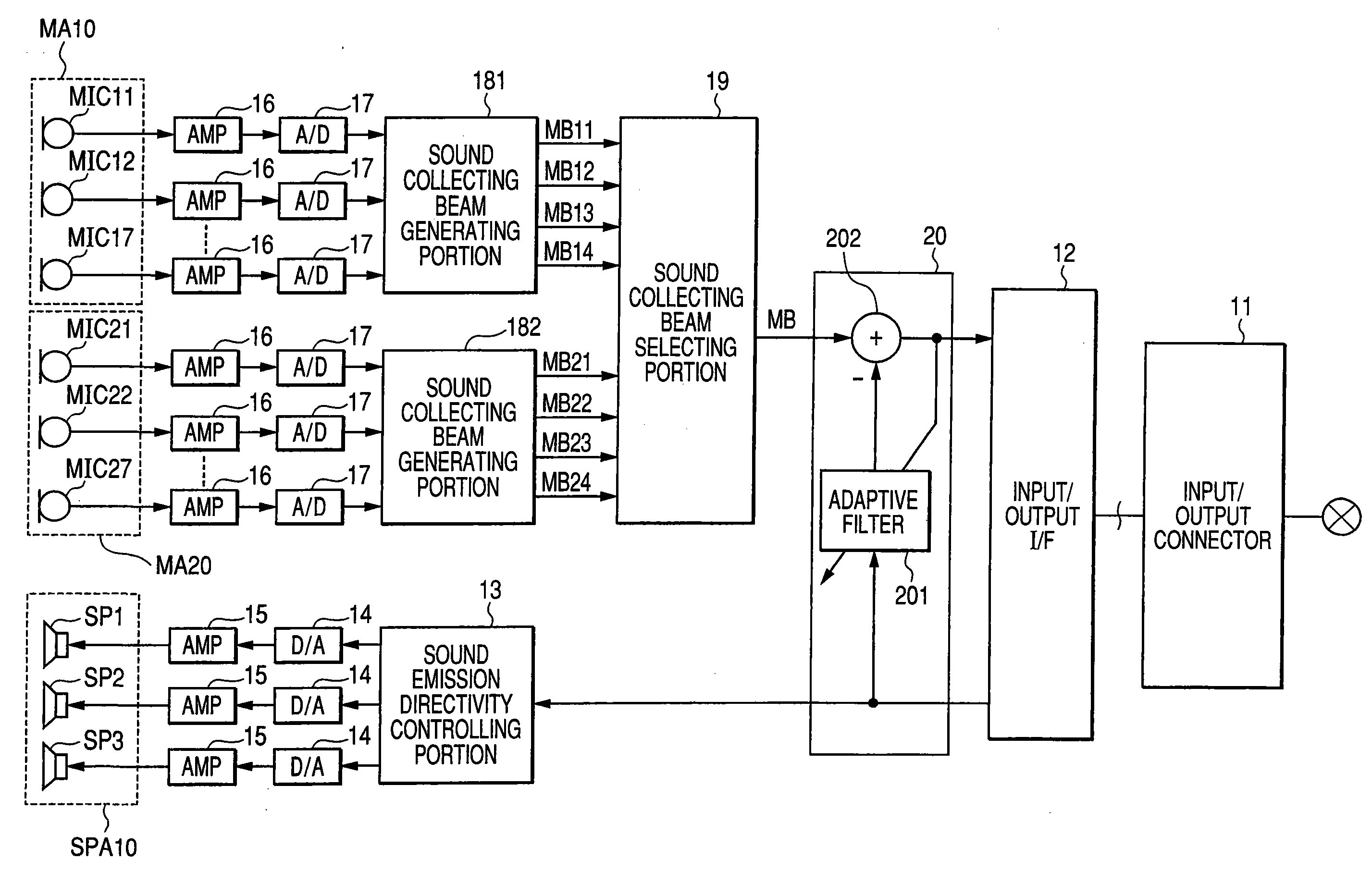
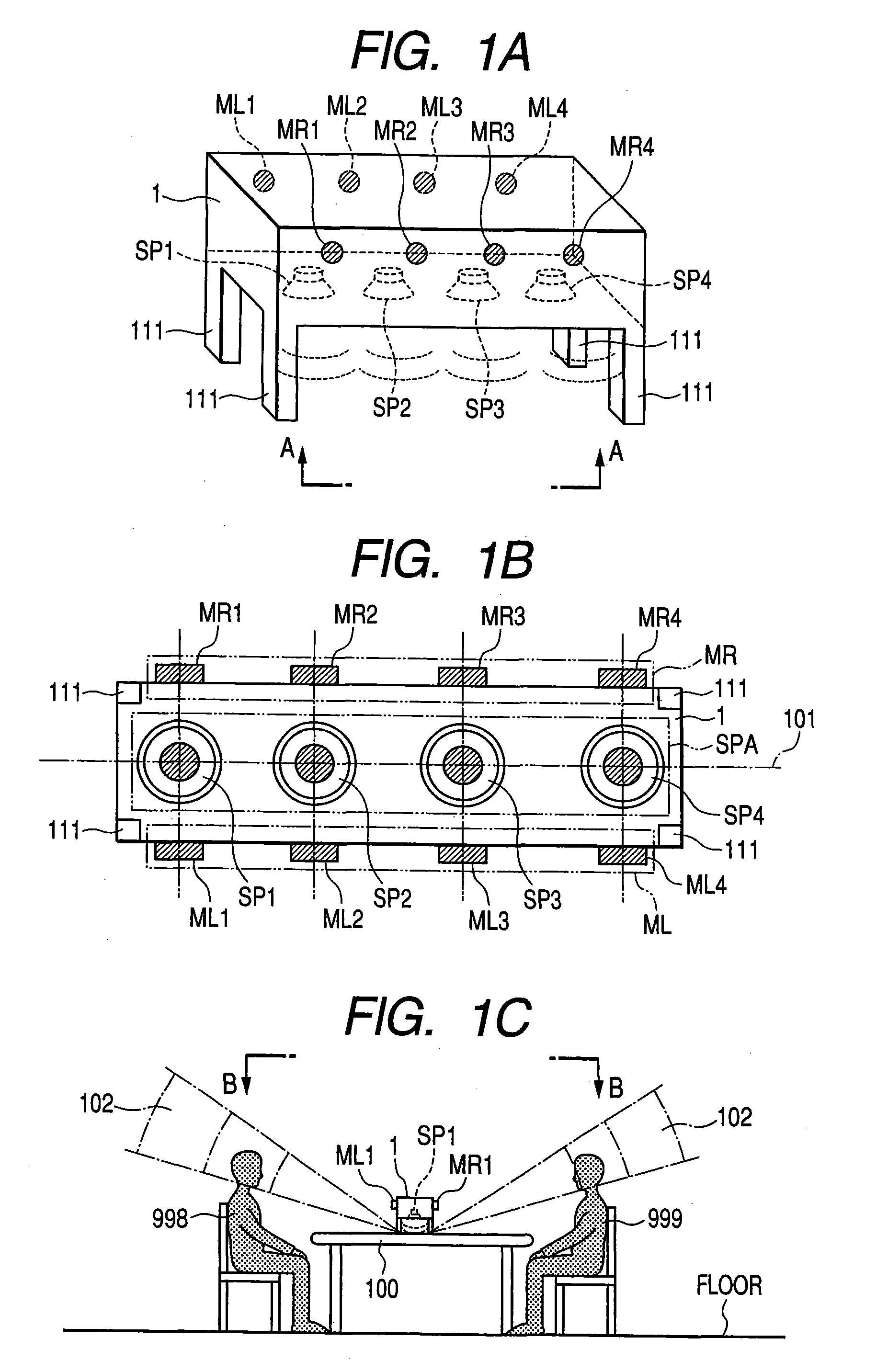
[0060]A configuration and a using mode of a remote conference apparatus as a first embodiment of the present invention will be explained with reference to FIGS. 1A to 1C hereinafter. The remote conference apparatus of the first embodiment provides such an equipment that a sound transmitted from the opposing equipment is output by using a speaker array to reproduce a position of a talker on the opposing equipment side, while a voice of a talker is picked up by using a microphone array to detect a position of the talker and then the picked-up voice and position information are transmitted to the opposing equipment.

[0061]FIGS. 1A to 1C shows an external view and a using mode of this remote conference apparatus. FIG. 1A is an external perspective view of the remote conference apparatus, and FIG. 1B is a bottom view showing the remote conference apparatus, taken along an A-A arrow line. Also, FIG. 1C is a view showing a using mode of the remote conference apparatus.

[0062]As shown in FIG....

second embodiment

[0114]Next, a remote conference apparatus according to a second embodiment will be explained with reference to FIG. 7 hereunder. This embodiment is an application of the first embodiment shown in FIG. 4, and their explanation will be applied correspondingly by affixing the same reference symbols to the same portions. Also, FIG. 3 is referred auxiliarily to in explanation of the sound collecting beam.

[0115]In the first embodiment, the second estimating portion 252 estimates on which side the true sound source exists on the assumption that the true sound source resides in either of pairs of sound collecting areas whose difference signal is large. In the second embodiment, the first beam generating portion 231 and the second beam generating portion 232 have detailed position searching beam (narrow beam) generating functions 2313, 2323 of searching in detail the sound collecting area in which the true sound source that the second estimating portion 252 estimated exists to detect the sou...

third embodiment

[0123]Next, a transmitting portion of a remote conference apparatus according to a third embodiment of the present invention will be explained with reference to FIG. 8 hereunder. FIG. 8 is a block diagram of this transmitting portion. The transmitting potion 2 of the equipment of the present embodiment is different in that the outputs of the A / D converters 211, 212 are the inputs of the difference value calculating circuit 22, a third beam generating portion 237 for generating the sound collecting beam by using the output signal of the difference value calculating circuit 22 is provided, a fourth beam generating portion 238 and a fifth beam generating portion 239 are provided, and the selectors 271, 272 are neglected. The same reference symbols are affixed to remaining portions, and above explanation will be applied correspondingly to remaining portions. Then, different points and important points of the equipment of the present embodiment will be explained hereunder.

[0124]As shown ...


PUM


Abstract

A speaker array and microphone arrays positioned on both sides of the speaker array are provided. A plurality of focal points each serving as a position of a talker are set in front of the microphone arrays respectively symmetrically with respect to a centerline of the speaker array, and a bundle of sound collecting beams is output toward the focal points. Difference values between sound collecting beams directed toward the focal points that are symmetrical with respect to the centerline are calculated to cancel sound components that detour from the speaker array to microphones. Then, it is estimated based on totals of squares of peak values of the difference values for a particular time period that the position of the talker is close to which one of the focal points, and the position of the talker is decided by comparing the totals of the squares of the peak values of the sound collecting beams directed to the focal points that are symmetrical mutually.

Description

TECHNICAL FIELD[0001]The present invention relates to equipment having microphone arrays and speaker arrays to reproduce a received sound and a sound field and, more particularly, the technology to specify a position of a talker or a sound source from the microphone array.BACKGROUND ART[0002]In the prior art, the means for receiving a sound on the transmitter side and reproducing a sound field of the sound on the transmitter side has been proposed (see Patent Literatures 1 to 3). In such equipment, sound signals picked up by a plurality of microphones, etc. are transmitted, and the sound field on the transmitter side is reproduced by using a plurality of speakers on the receiver side. Such equipment possesses the advantage that a position of a talker can be specified by the sound.[0003]In Patent Literature 1, the method of creating stereophonic sound information by transmitting sound information received by a plurality of microphone arrays and then outputting the sound information f...

Claims


Application Information

Patent Timeline
Patent Type & Authority Applications(United States)
IPC IPC(8): H04R3/00
CPCH04R1/403H04R1/406H04R3/005H04R2430/20H04R2201/403H04R2430/03H04R3/12
Inventor ISHIBASHI, TOSHIAKISUZUKI, SATOSHITANAKA, RYOUKAI, SATOSHI
Owner YAMAHA CORP
Why Eureka
Try Eureka