Methods to create fluorescent biosensors using aptamers with fluorescent base analogs
- Summary
- Abstract
- Description
- Claims
- Application Information
AI Technical Summary
Benefits of technology
Problems solved by technology
Method used
Image
Examples
example 1
Fluorescent Human α-Thrombin Aptamer
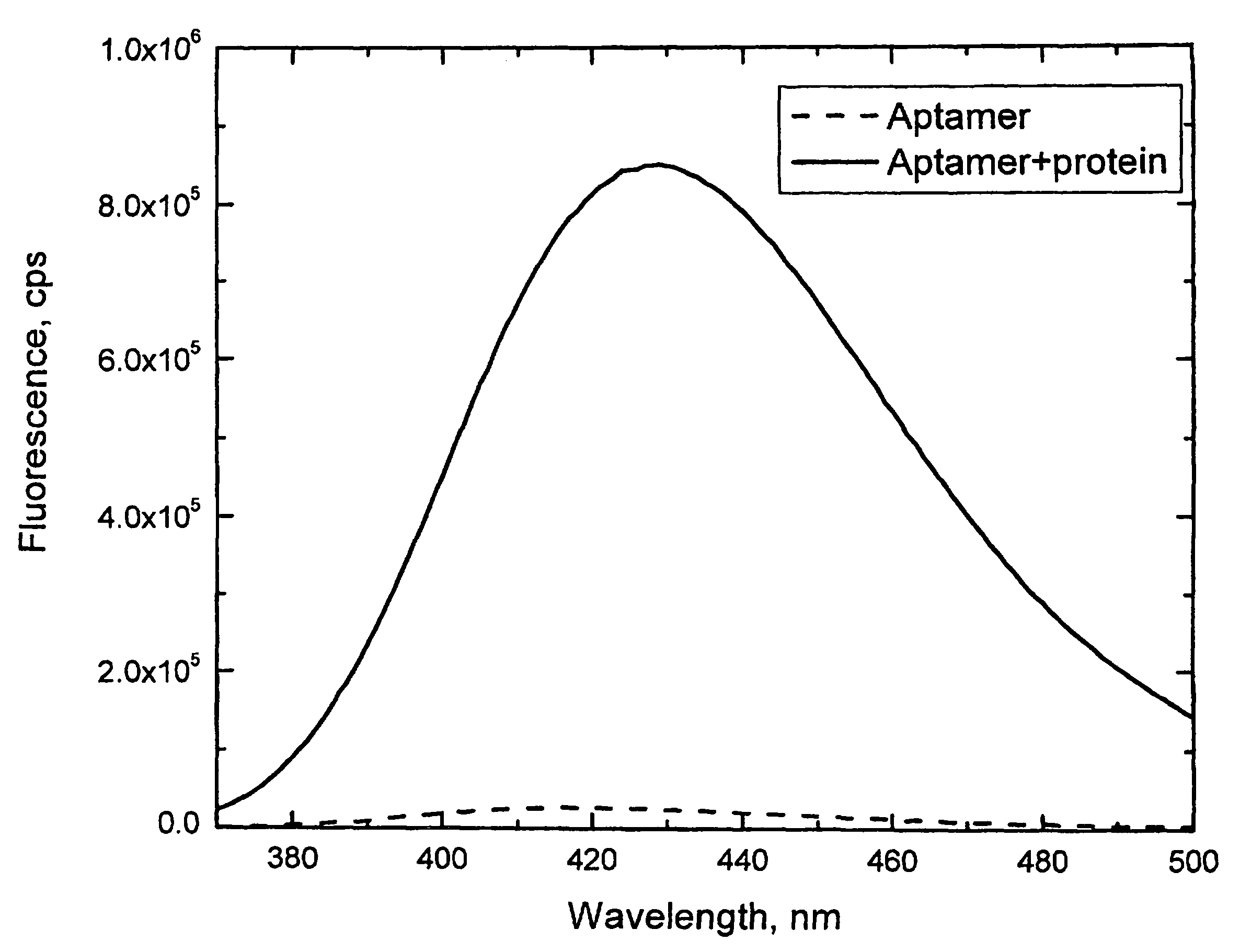
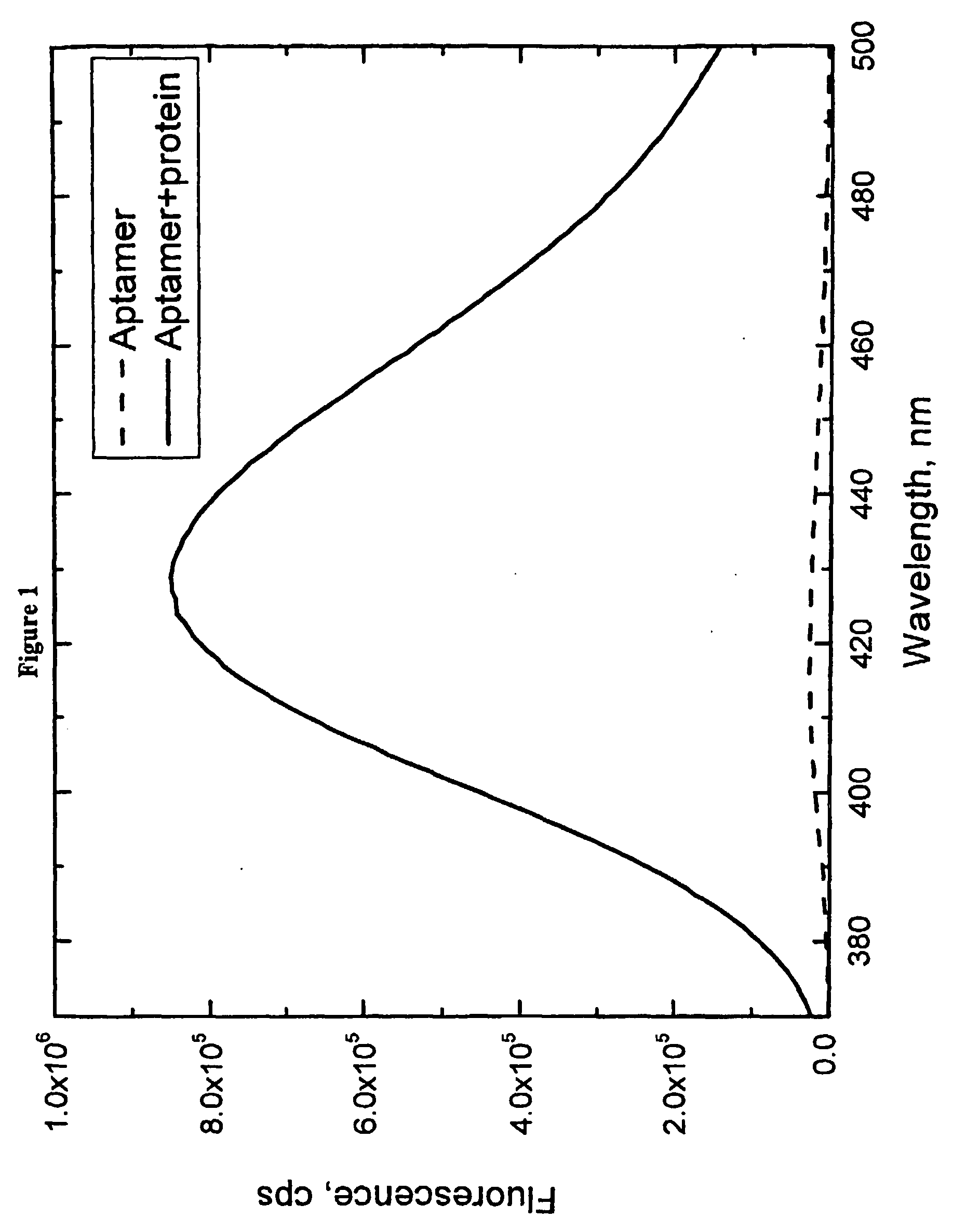
[0055]A fluorescent aptamer for the human α-thrombin protein was generated, with the sequence 5′-GGTTGGTGTGGTTGG-3′ (SEQ ID NO:4). (L. C. Bock, L. C. Griffin, J. A. Latham, E. H. Vermaas, J. J. Toole, Nature 355, 564-566 (Feb. 6, 1992)) This aptamer was modified by replacing the thymine (“T”) at position 7 with 6MAP using standard synthetic solid-state DNA synthesis techniques. Fluorescence of 6MAP is strongly dependent on the media surrounding this molecule. Its fluorescence is strongly quenched when 6MAP is base stacked within the single or double stranded DNA aptamer. Unstacking of 6MAP within the aptamer upon binding to α-thrombin leads to nearly 33-fold increase in its fluorescence (see FIG. 1 and table 1). Thus, incorporation of 6MAP at this location leads to a large increase in fluorescence signal of polynucleotide when it binds to its ligand.
[0056]The example was reproduced using another fluorescent base analog, 2-aminopurine. Incorporatio...
example 2
Fluorescent IgE Immunoglobulin Aptamer
[0057]In this example, a signaling aptamer of IgE immunoglobulin was made using secondary DNA structure calculation algorithms to minimize the set of possible modifications for screening.
[0058]The consensus sequence of IgE aptamer published in [1] is:
(SEQ ID NO: 5)5′ GGG GCA CGT TTA TCC GTC CCT CCT AGT GGC GTG CCCC 3′.
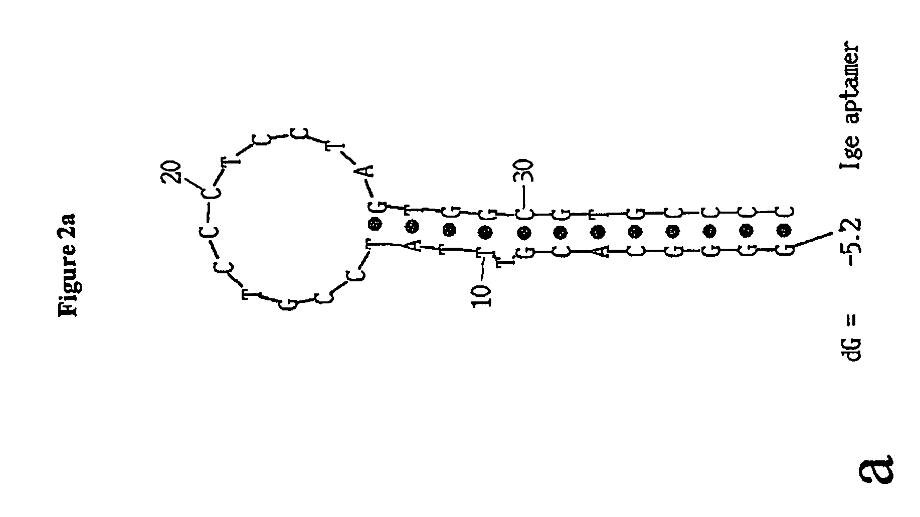
[0059]The secondary structure calculation for this aptamer is presented in FIG. 2a, which suggests that the aptamer folds into a hairpin conformation with a 14 base pair stem and 12 bases loop. Based on the calculated aptamer secondary structure, it can be hypothesized that the IgE immunoglobulin binding site consists mostly of loop nucleotides. Therefore, screening of the loop bases for signaling effect was performed using 2-aminopurine as a signaling molecule. Twelve different aptamers were synthesized, in which each of the bases in the loop region were replaced with 2-aminopurine. Screening was performed on unpurified aptamers (...
example 3
Fluorescent Platelet-Derived Growth Factor B Aptamer
[0061]In this example, a signaling aptamer of platelet-derived growth factor B (PDGF-B) [2] was made using secondary DNA structure calculation algorithms to minimize the set of possible modifications for screening.
[0062]An aptamer to platelet-derived growth factor B (PDGF B) was previously described in [2]. The sequence of the minimized aptamer is:
(SEQ ID NO: 6)5′ CAC AGG CTA CGG CAC GTA GAG CAT CAC CAT GAT CCTGTG 3′.
[0063]Secondary structure calculations for this aptamer yielded two different possible structures (see FIG. 3a). This suggested that the protein binding site is in the center of the aptamer, at the three helix junction. Therefore, screening of bases which form loops in the center of the aptamer was performed. Five aptamer sequences with 2-aminopurine at positions 20-22 and 32, 33 (i.e., the nucleotide positions at the center of the aptamer) were synthesized and screened for a fluorescence signal change caused by PDGF-B...
PUM
| Property | Measurement | Unit |
|---|---|---|
| Fraction | aaaaa | aaaaa |
| Fluorescence | aaaaa | aaaaa |
Abstract
Description
Claims
Application Information
 - R&D
- Intellectual Property
- Life Sciences
- Materials
- Tech Scout
- Unparalleled Data Quality
- Higher Quality Content
- 60% Fewer Hallucinations
Browse by: Latest US Patents, China's latest patents, Technical Efficacy Thesaurus, Application Domain, Technology Topic, Popular Technical Reports.
© 2025 PatSnap. All rights reserved.Legal|Privacy policy|Modern Slavery Act Transparency Statement|Sitemap|About US| Contact US: help@patsnap.com


