Fluid filter separator and method

a technology of filter separator and filter separator, which is applied in the direction of filtration separation, combustible gas purification/modification, separation process, etc., can solve the problems of high cost of stacked ceramic discs, exotic elements, etc., and achieves the effect of being cheap and efficien

Inactive Publication Date: 2009-03-05
CAREW BAYNE
View PDF44 Cites 18 Cited by
  • Summary
  • Abstract
  • Description
  • Claims
  • Application Information

AI Technical Summary

Benefits of technology

[0007]In one preferred embodiment, the fluid separator filter is a gas separator which may be utilized, for example, to purify syngas. As will be understood by those skilled in this art, a mixture of carbon monoxide and hydrogen is sometimes referred to as fuel gas to define the ultimate use of the gas. However, as used herein, the term “syngas” includes primarily a mixture of carbon monoxide and hydrogen and includes fuel gas. However, as discussed further below, the separator filter of this invention may also be used to filter, separate and purify various gases and liquids. In the disclosed embodiment, where the gas separator filter is utilized to purify syngas, the suspended metal oxide particles may be fine particles of calcium oxide, such as cement kiln dust, which is relatively inexpensive and efficient. Further, in the disclosed embodiment of the gas separator filter, the radial mixing blades are fixed to a rotating central shaft and each blade includes a radial central portion extending perpendicular to the central shaft, a first side portion adjacent the central shaft extending radially and circumferentially from the central shaft at an obtuse angle to the radial central portion circulating fluid upwardly adjacent the central shaft and a second side portion extending from an opposite side of the central radial portion, radially spaced from the first side portion, adjacent a distal end of a central portion extending radially and circumferentially at an obtuse angle to the radial central portion, circulating fluid downwardly adjacent a distal end of the radial mixing blades. This configuration of the radial blades is very efficient to circulate the suspended adsorbent particles upwardly adjacent the central axis of the fluid separation chamber and downwardly adjacent the distal ends of the radial mixing blades, removing unwanted fluids.

Problems solved by technology

The barriers to bringing a high temperature solid oxide fuel cell (SOFC) to market include the high cost of stacked ceramic discs, their interconnects and exotic elements, which are subject to corrosion from CO2 / H2O formed in the oxidation process.

Method used


Image

  • Fluid filter separator and method
  • Fluid filter separator and method
  • Fluid filter separator and method

Examples


second embodiment

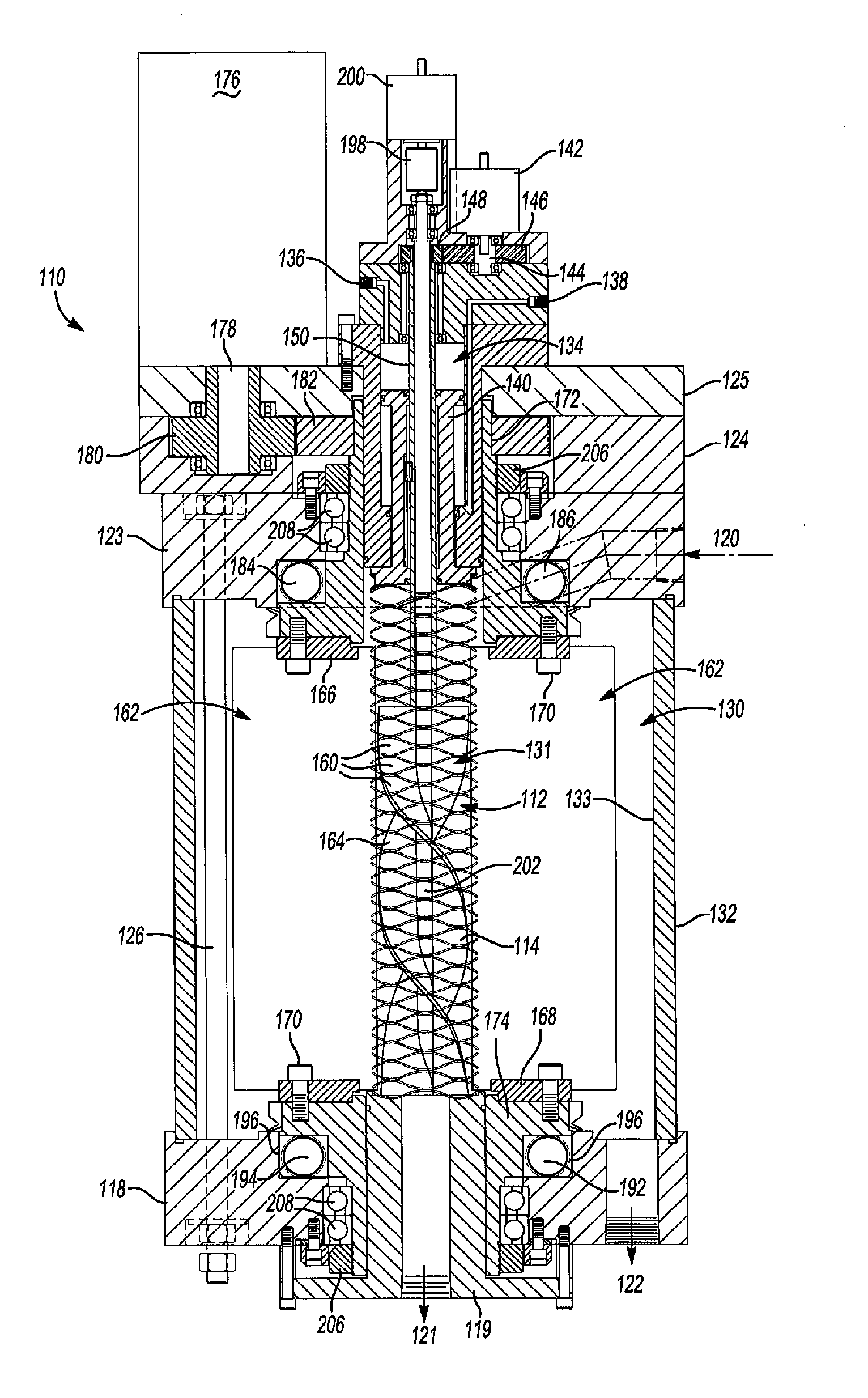
[0039]the filter apparatus 110 of this invention illustrated in FIGS. 7 to 12 may be characterized as a centrifugal filter apparatus or more specifically a dual-chambered centrifugal and compressive filtration apparatus for separating waste solids from fluids including, for example, waste solids in oils, water and gas. The elements of the centrifugal filter apparatus 110 are numbered where appropriate in the same sequence as the filter apparatus 10 described above, but in the 100 series to reduce the requirement for a detailed description of like components. The disclosed embodiment of the filter apparatus 110 includes a central annular filter element 112 which, in the disclosed embodiment, is a continuous flexible resilient generally cylindrical helical coil including a plurality of interconnected generally circular helical coils 114 as described above with reference to the filler element 12. However, the centrifugal filter apparatus of this invention may alternatively include any ...

third embodiment

[0054]FIGS. 13 to 18 of this application disclose a filter apparatus or separator filter apparatus 210 which may be used to filter and separate or purify various fluids, including liquids and gases. In one disclosed embodiment, the filter separator 210 may be used to purify syngas and remove suspended waste particulates and waste gaseous oxides of nitrogen, sulfur or carbon. It is well known that in the process of gasification of biomaterials, particulates in the micron size range as well as the noted contaminating oxides are generated. These contaminate the syngases (CO / H2). CaO (hot lime) or other metal oxides in the gas separation to form CaCO3, CaSO4 and Ca[NO3]2 as discussed further below, a metal oxide, such as CaO separates contamination gases from the fuel gases or syngases which can be subsequently stripped of gaseous contaminants and regenerated by periodic heating at calcination temperatures in the 1200° F. range as also discussed below.

[0055]The filter separator 210 show...


PUM

PropertyMeasurementUnit
obtuse angleaaaaaaaaaa
flexibleaaaaaaaaaa
temperatureaaaaaaaaaa

Abstract

A filter separator and method, including an annular microfilter and a separation chamber within the microfilter including a plurality of mixing blades circulating fluid upwardly and downward within the chamber. When the apparatus is used to purify syngas, adherent metal oxide particles are circulated in the chamber to adsorb waste oxides. The apparatus is purged by injecting hot CO2 free gas into the chamber through the filter and the filter pores may be expanded during purging.

Description

RELATED APPLICATIONS[0001]This application claims priority to U.S. Provisional Application Ser. No. 60 / 986,667, filed Nov. 9, 2007, and is a continuation-in-part application of U.S. Ser. No. 12 / 186,421, filed Aug. 5, 2008, which application was a continuation-in-part application of U.S. Ser. No. 11 / 942,525, filed Nov. 19, 2007, which application was a continuation-in-part application of U.S. Ser. No. 11 / 531,986, filed Sep. 14, 2006, which application was a divisional application of U.S. Ser. No. 10 / 863,798 filed Jun. 5, 2004, now U.S. Pat. No. 7,122,123, issued Oct. 17, 2006, which application was a divisional application of U.S. Ser. No. 09 / 931,510, filed Aug. 16, 2001, now U.S. Pat. No. 6,761,270, issued Jul. 13, 2004, which application claims priority to U.S. Provisional Patent Application No. 60 / 225,895, filed Aug. 17, 2000.FIELD OF THE INVENTION[0002]This invention relates to a fluid filter separator, mixer and method particularly, but not exclusively for purifying syngas and o...

Claims


Application Information

Patent Timeline
Patent Type & Authority Applications(United States)
IPC IPC(8): B01D53/08B01D53/02B01F7/00B01F15/02B01F15/06
CPCA01K63/045B01D29/15Y02C10/08C10K1/024B01D2275/302B01D2259/4009B01D2259/40086B01D2257/504B01D2257/404B01D2257/302B01D2256/20B01D2256/16B01D2253/112B01D2251/602B01D2251/404B01D2201/184B01D2201/0415B01D53/08B01D46/403B01D29/48B01D36/003B01D37/025B01D29/23B01D29/58B01D29/606B01D29/668B01D29/902B01D29/925B01D29/906B01D29/908Y02C20/40Y02P20/151
Inventor CAREW, BAYNE
Owner CAREW BAYNE
Why Eureka
Try Eureka