Thermal spraying nozzle device and thermal spraying system using the same

a technology of thermal spraying and nozzles, which is applied in the direction of liquid spraying apparatus, coatings, metal material coating processes, etc., can solve the problems of difficult to control the state of lamination difficult to control the lamination state on the base material, so as to achieve accurate thermal spraying and form a uniform and compact metal laminate

Inactive Publication Date: 2009-03-05
KOBE STEEL LTD
View PDF2 Cites 28 Cited by
  • Summary
  • Abstract
  • Description
  • Claims
  • Application Information

AI Technical Summary

Benefits of technology

[0026]Further, the thermal spraying material inserting section is constructed so as to permit insertion of plural pieces of the thermal spraying material into the nozzle, and front end portions of the thermal spraying material pieces are formed as discharging electrodes for generating an arc discharge, thereby constituting the thermal spraying material melting means. In this case, if there are provided a hollow chamber on the nozzle inlet side and two carrier gas supply pipes communicating with the hollow chamber to introduce the carrier gas as counter flows and if cylindrical thermal spraying material inserting sections are disposed respectively at positions where they collide with the carrier gas discharged from the carrier gas supply pipes toward the hollow chamber, it is possible to diminish a rotating flow in a section perpendicular to the intra-nozzle flow direction. As a result, it is possible to diminish a flow component which blows a melted droplet at an arc melting point against the wall surface.
[0042]According to the thermal spraying system of the present invention, it is possible to accurately control the thermal spraying material to be laminated onto the base material. Further, according to the thermal spraying system which controls the attitude of the nozzle on the basis of three-dimensional CAD data, it is possible to form a three-dimensional solid model accurately.

Problems solved by technology

Consequently, a gas flow is disturbed by the thermal spraying material which projects so as to obstruct a flow path and it is difficult to control the state of lamination on the base material.
According to this technique described in Patent Literature 3, the melted ball can be ejected in a uniform size, but the melted ball is flied with a gas flow after ejected radially from the nozzle, so also in this case it is difficult to control the state of lamination on a base material.

Method used


Image

  • Thermal spraying nozzle device and thermal spraying system using the same
  • Thermal spraying nozzle device and thermal spraying system using the same
  • Thermal spraying nozzle device and thermal spraying system using the same

Examples


Embodiment Construction

[0061]The present invention will be described in detail hereinunder on the basis of the embodiments illustrated in the drawings.

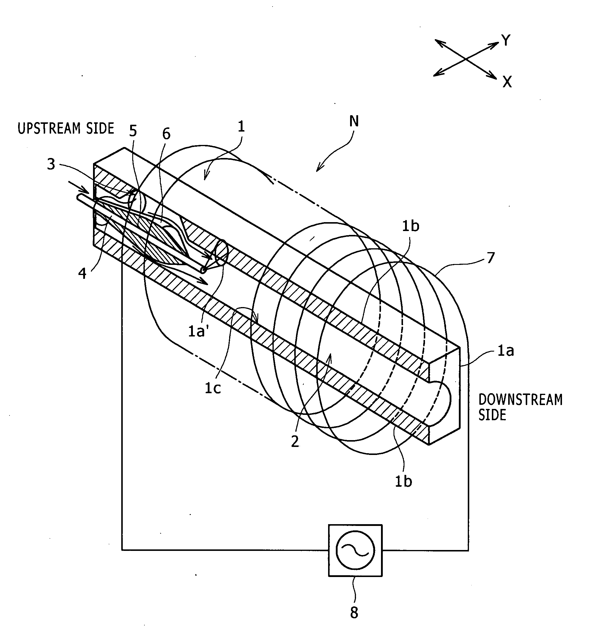
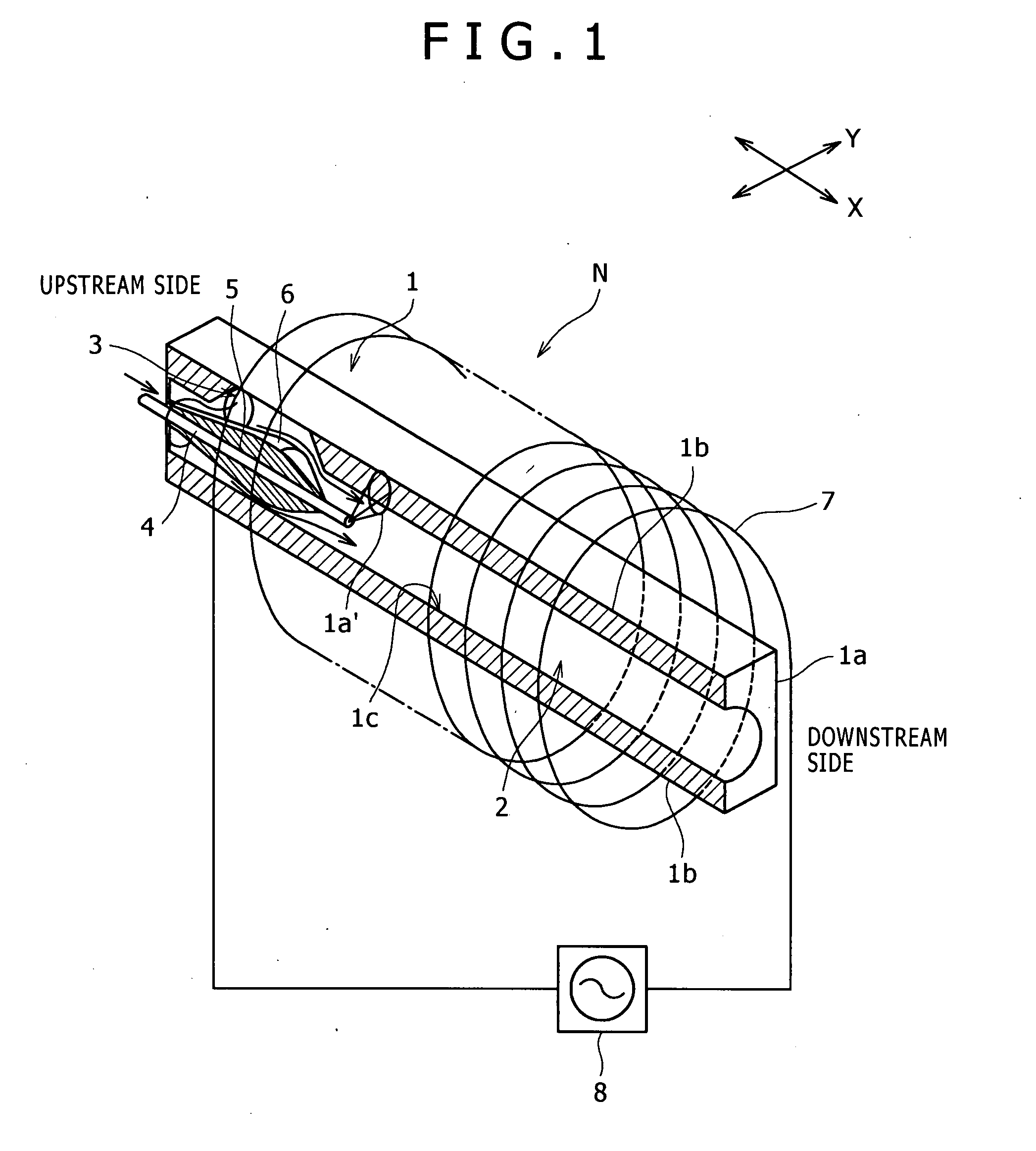
[0062]FIG. 1 illustrates the construction of a thermal spraying nozzle device N according to the present invention.

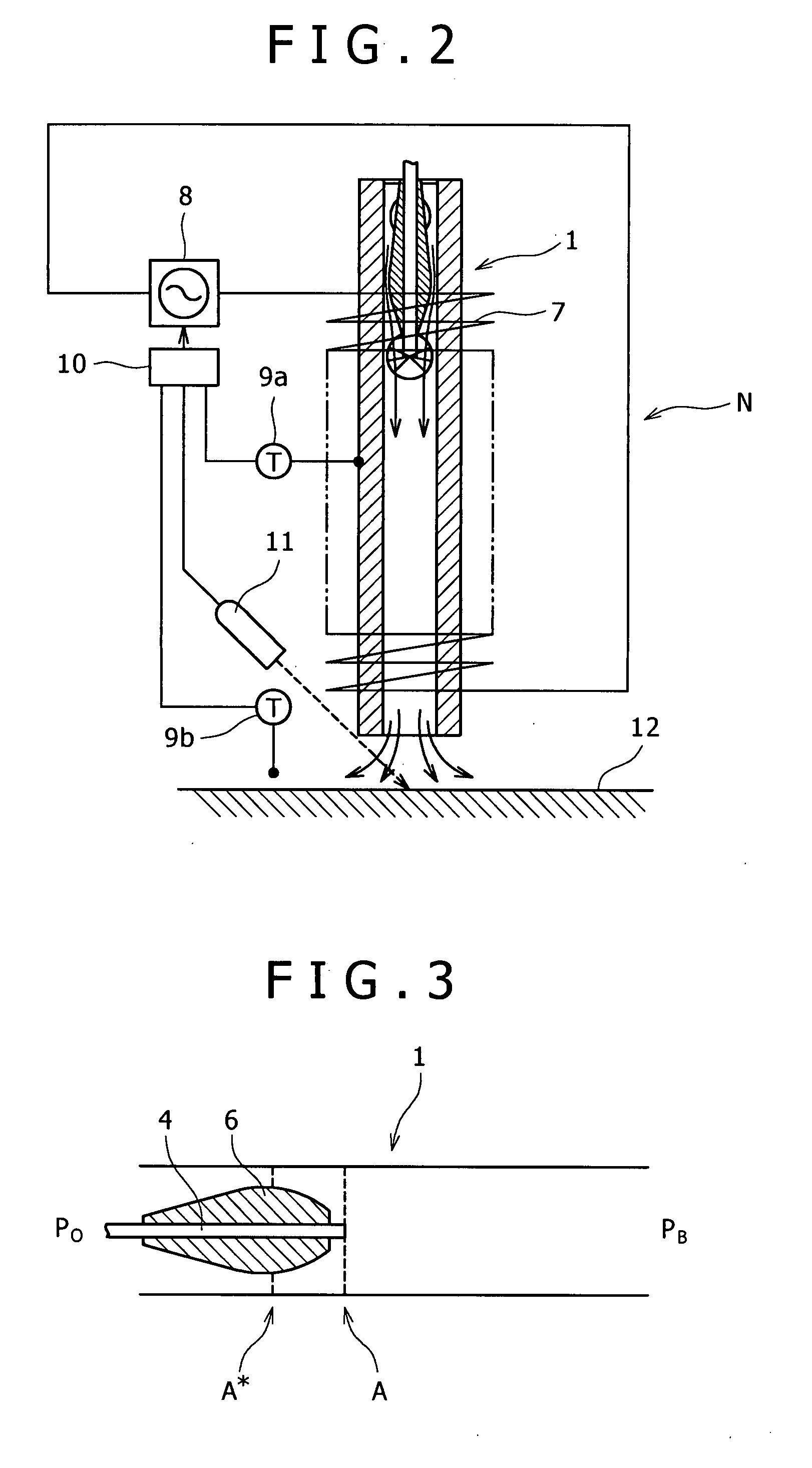
[0063]In the same-figure, a passage 2 having a constant inside diameter is formed in the interior of the nozzle 1 in the nozzle axis direction. On an upstream side (in a carrier gas flow direction) of the passage 2 is formed a carrier gas supply port 3. Further, on the upstream side and on the central axis of the passage 2 is disposed a guide (a thermal spraying material inserting section) 5 which is a hollow pipe of a circular section for feeding out wire 4 as a thermal spraying material toward a downstream side.

[0064]An outer surface of the guide 5 is expanded in diameter gradually toward the downstream side, whereby there is formed a throat portion 6 providing a narrowest annular gap between it and an inner surface of the passage 2. On the d...


PUM

PropertyMeasurementUnit
pressureaaaaaaaaaa
pressureaaaaaaaaaa
diameteraaaaaaaaaa

Abstract

[Subject]A thermal spraying nozzle device capable of accurately forming a uniform and compact metal laminate, as well as a thermal spraying system using the thermal spraying nozzle device, are to be provided.[Solution]A thermal spraying nozzle device wherein carrier gas is introduced into an inlet side of a nozzle (1) to form a supersonic gas flow in the entire region inside the nozzle and a thermal spraying material is atomized and ejected by the gas flow, the thermal spraying nozzle device comprising a thermal spraying material inserting section (5) for insertion therethrough of the thermal spraying material (4) formed in a linear shape into the nozzle (1) from the inlet side substantially in parallel with the gas flow and a laser device for heating and melting the thermal spraying material projected from the thermal spraying material inserting section in the vicinity of a front end of the thermal spraying material inserting section, particles of the thermal spraying material melted and atomized by the laser device being cooled quickly by the supersonic gas flow in the nozzle (1) and ejected in a solidified or semi-solidified state.

Description

TECHNICAL FIELD [0001]The present invention relates to a thermal spraying nozzle device capable of being used for various purposes as a thermal spraying nozzle to form a surface coating layer on a base material and as an injection nozzle to form a three-dimensional laminate, as well as a thermal spraying system using the thermal spraying nozzle device.BACKGROUND ART[0002]Today, a cold spraying technique is becoming more and more popular in which a material is brought into collision with a base material while it is in a solid phase as a supersonic flow together with an inert gas without being melted or gasified, thereby forming a film (see, for example, Japanese Patent Laid-Open No. 2004-76157, Patent Literature 1).[0003]The cold spraying technique, unlike other thermal spraying methods, is advantageous in that there occurs no change in characteristics of a material used under the application of heat and that it is possible to suppress oxidation in the film formed. Besides, the cold ...

Claims


Application Information

Patent Timeline
Patent Type & Authority Applications(United States)
IPC IPC(8): B05C5/00
CPCB05B12/084C23C4/12B05B7/228C23C4/124B05B7/224C23C4/122C23C4/126C23C4/129
Inventor ODA, TSUYOSHIHATA, HIDEOMAEDA, YASUSHIFUKUTANI, KAZUHISA
Owner KOBE STEEL LTD
Why Eureka
Try Eureka