
Docking stand for analytical instrument

a technology for analytical instruments and stands, applied in instruments, optical radiation measurement, separation processes, etc., can solve the problems of difficult to securely convey certifications or other information about analyzed materials when the materials change hands, take time to re-analyse the pieces and then move the pieces to separate stockpiles, and require a large amount of real esta

Active Publication Date: 2009-03-05
THERMO NITON ANALYZERS
View PDF17 Cites 7 Cited by
  • Summary
  • Abstract
  • Description
  • Claims
  • Application Information

AI Technical Summary

Benefits of technology

[0011]Yet an embodiment of the present invention provides a method for automatically preventing unsafe operation of an analytical instrument that can operate in at least two different modes. The method includes automatically determining if the analytical instrument is mounted on a stand. If the analytical instrument is determined to be mounted on the stand, the method may include operating the analyzer according to a first of the at least two different modes only if a safety device on the stand has been activated. However, if the analytical instrument is determined not to be mounted on the stand, the method may include operating the analytical instrument according to a second of the at least two different modes, without determining if the safety device has been activated.
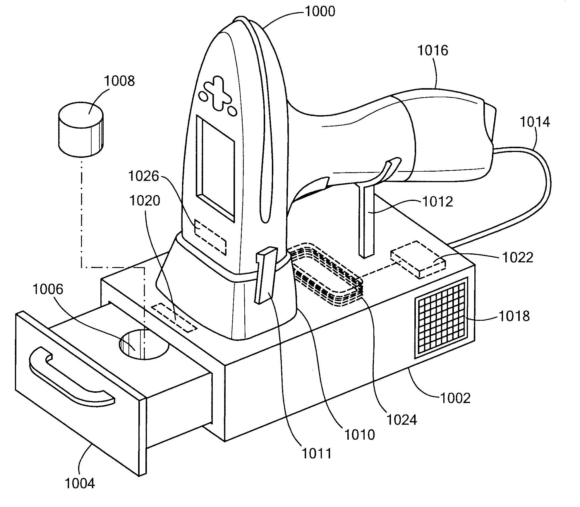
[0016]An embodiment of the present invention provides a stand for an analytical instrument. The stand includes a receiver for detachably docking an analytical instrument that produces a beam of penetrating radiation. The stand also includes a shield that is substantially opaque to the radiation produced by the analytical instrument. The stand also includes an interlock that prevents production of the radiation by the analytical instrument when the shield is in a first position and allows production of the radiation when the shield is in a second position.

Problems solved by technology

Re-analyzing the pieces and then moving the pieces to the separate stockpiles takes time.
Even if the pieces were originally segregated according to alloy, requiring a separate stockpile for each material composition requires a large amount of real estate, because each stockpile must be separated from the other stockpiles by enough space to operate material moving equipment.
However, securely conveying certifications or other information about analyzed materials when the materials change hands is difficult, particularly if the materials are conveyed through a long chain of ownership.

Method used


Image

  • Docking stand for analytical instrument
  • Docking stand for analytical instrument
  • Docking stand for analytical instrument

Examples


Embodiment Construction

Description

[0034]The contents of U.S. Provisional Patent Application Nos. 60 / 891,408, titled “Hand-Held, Self-Contained Optical Emission Spectroscopy (OES) Analyzer,” filed Feb. 23, 2007, and 60 / 889,465, titled “Small Spot X-Ray Fluorescence (XRF) Analyzer,” filed Feb. 12, 2007, are hereby incorporated by reference herein.

Storing Analytical Information in Association with an Analyzed Sample

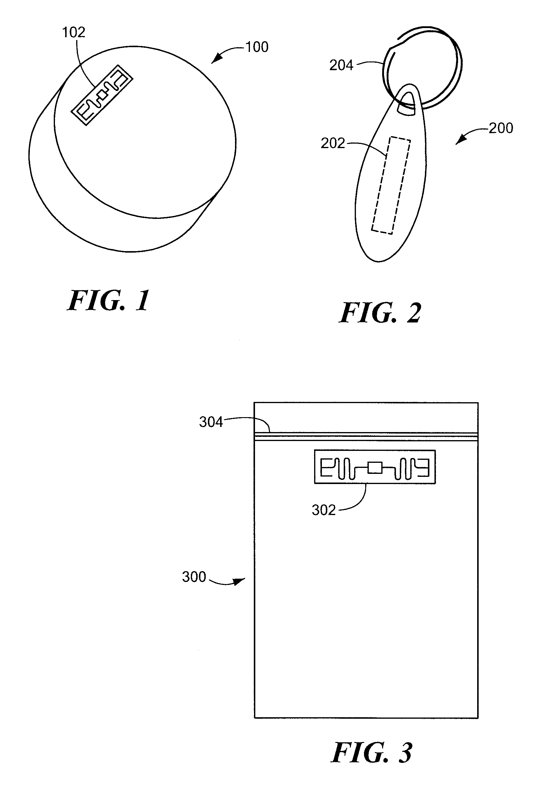
[0035]In accordance with embodiments of the present invention, methods and apparatus are disclosed for storing information related to an analyzed substance (also referred to as a “sample” or, equivalently, as an “analyte”), such as a metal, soil, a plastic or a composite. The information may be stored in a contactless memory. The term “contactless memory,” as used herein, means that the memory, be it read-only or read / write, may be read without electrical contact with the memory and in some embodiments may be written without contact. Exemplary contactless memories include, without limitation: pass...


PUM


Abstract

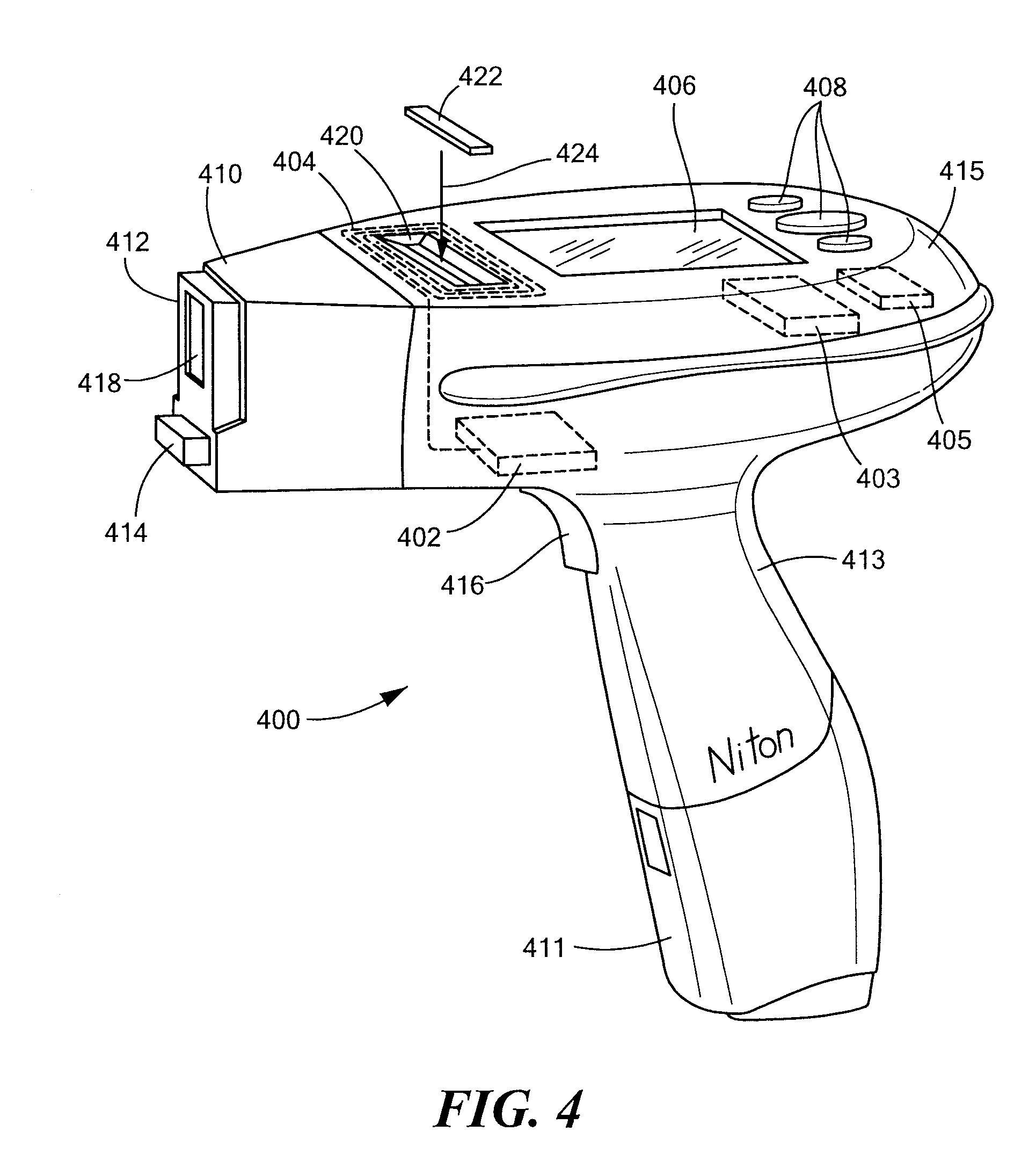
An analytical instrument may be docked in a stand. The stand provides electrical power, cooling, gas to purge air from an analytical gap within the instrument and / or other supplies or services to the instrument. The stand contains a contactless memory, such as an RF-ID tag, which stores information about the supplies and / or services the stand is capable of providing to the instrument. The instrument reads the stand's contactless memory and automatically sets operational parameters of the instrument in accordance with the supplies and / or services the stand is capable of providing. Thus, the instrument may automatically operate in an enhanced mode, such as at a higher x-ray beam power, as a result of being mounted in the stand.

Description

CROSS REFERENCE TO RELATED APPLICATIONS[0001]This application claims the benefit of U.S. Provisional Patent Application No. 60 / 968,538, filed Aug. 28, 2007, titled “Contactless Memory Information Storage for Sample Analysis,” the entire contents of which are hereby incorporated by reference herein, for all purposes.TECHNICAL FIELD[0002]The present invention is also related to automatically setting operating parameters of an analytical instrument, based on capabilities of a stand, in which the instrument is docked.BACKGROUND ART[0003]Portable and bench-top x-ray fluorescent (XRF), optical emission spectrographic (OES) and other analytical instruments are used throughout the world for determining elemental and chemical compositions of samples, such as metals, soils and plastics. In some cases, results of these analyses are stored in the instruments or archived in company databases, etc., sometimes with user-entered identifying information, such as time and date of analysis, instrument...

Claims


Application Information

Patent Timeline
Patent Type & Authority Applications(United States)
IPC IPC(8): G01J5/04
CPCG01N21/65G01N35/00732G01N2035/00326G06K7/0008G01N2035/00861G01N2223/0766G01N2223/301G01N2035/00841
Inventor DUGAS, MICHAEL E.HAMILTON, MARKMARTIN, KENNETH P.
Owner THERMO NITON ANALYZERS
Learn More