Coated Tracheostomy Tube and Stoma Stent or Cannula

a tracheostomy tube and stoma stent technology, applied in the field of tracheostomy tubes and stoma stents or cannulas, can solve the problems of patient initial inability to speak, causing problematic salivary fistulas, raw and rough mucosal lining of nasal cavity, etc., to prevent movement or displacement

a tracheostomy tube and stoma stent technology, applied in the field of tracheostomy tubes and stoma stents or cannulas, can solve the problems of patient initial inability to speak, causing problematic salivary fistulas, raw and rough mucosal lining of nasal cavity, etc., to prevent movement or displacement

US20090062927A1Active Publication Date: 2009-03-05E BENSON HOOD LAB

Image

  • Coated Tracheostomy Tube and Stoma Stent or Cannula
  • Coated Tracheostomy Tube and Stoma Stent or Cannula
  • Coated Tracheostomy Tube and Stoma Stent or Cannula

Examples


Embodiment Construction

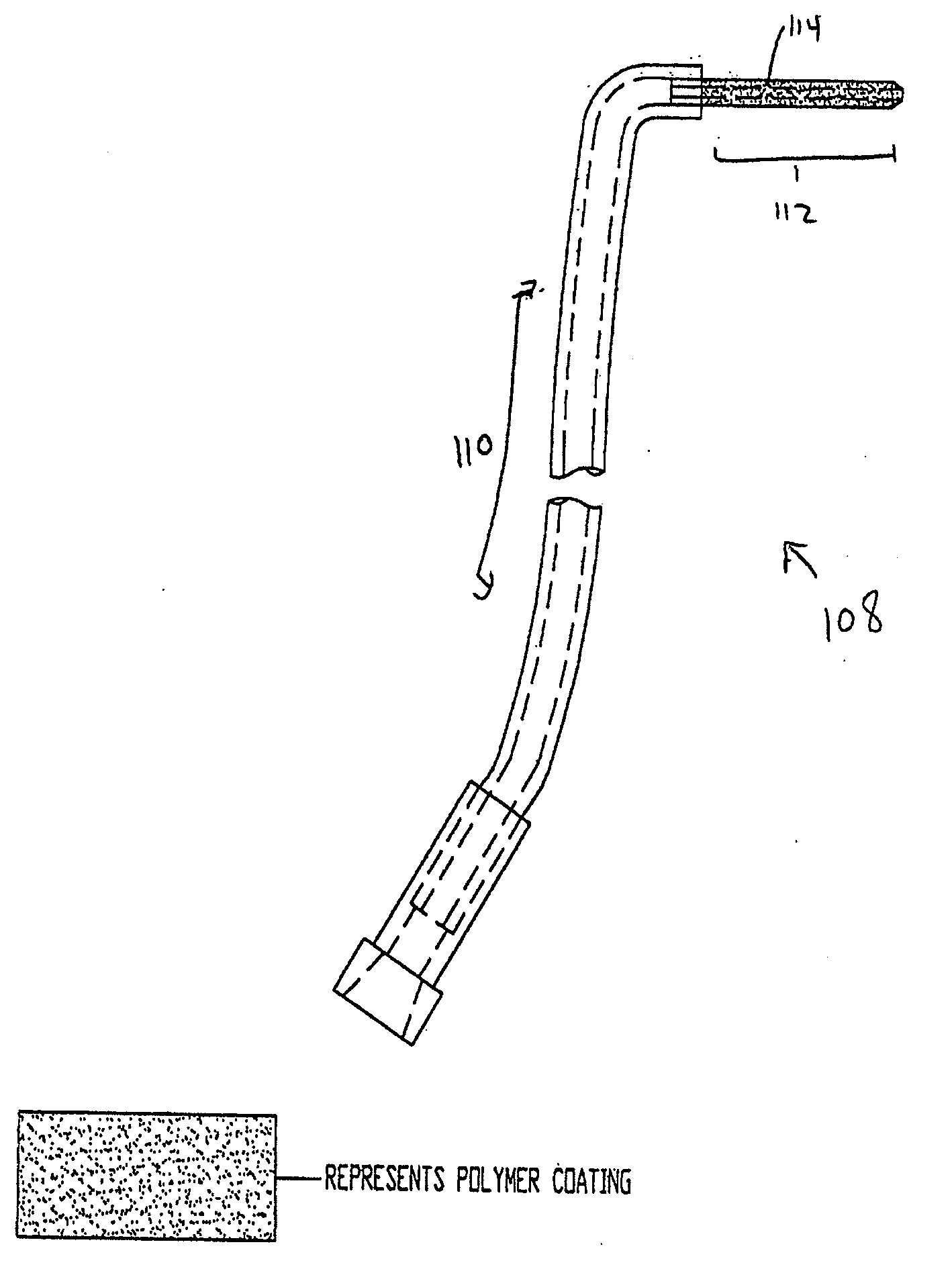
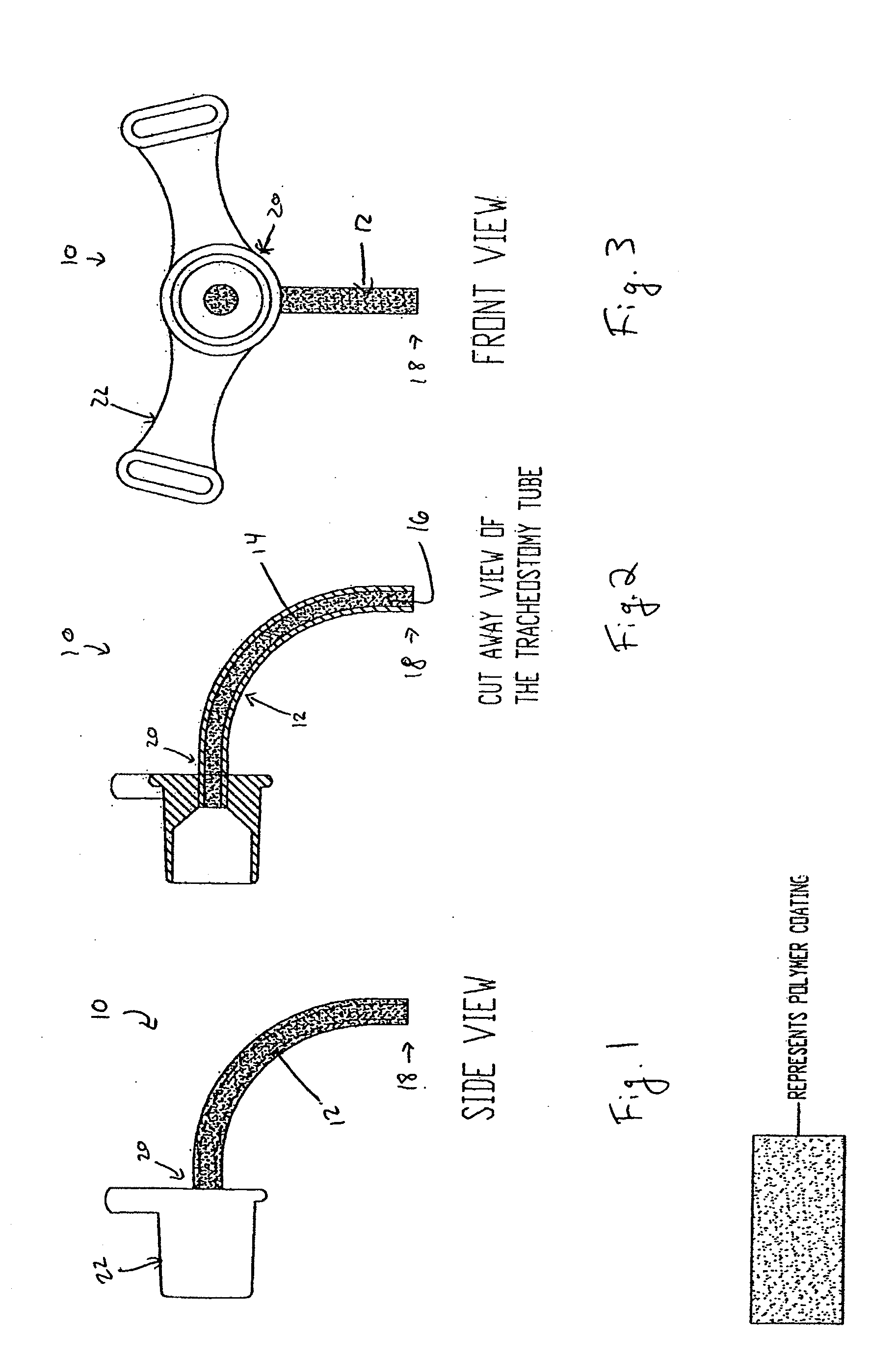
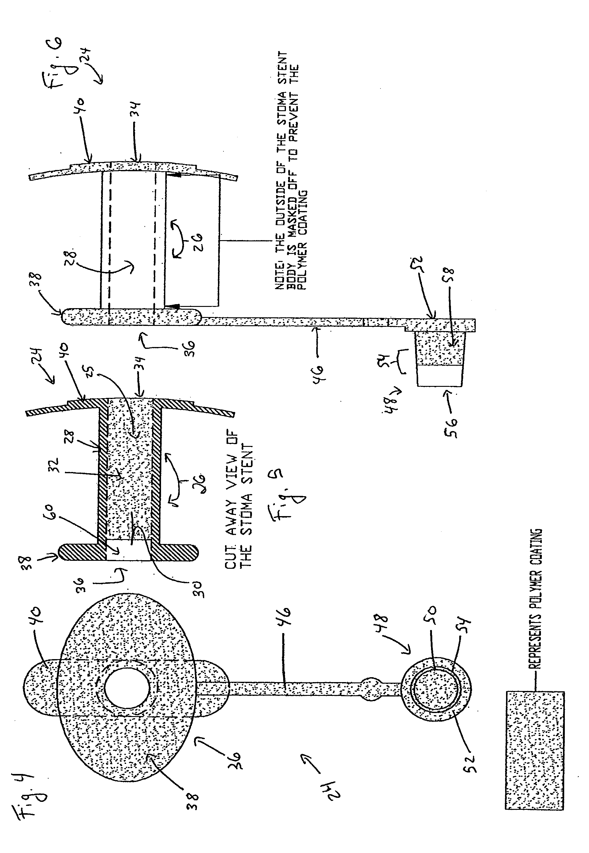
[0092]The present invention overcomes the shortcomings of the prior art by coating airway management devices with a protective polymeric coating. One suitable type of polymer is parylene. Parylene is the name for a series of polymers based on the monomer, para-xylene (p-xylene), or 1,4 dimethyl-benzene. There are three commercially available variations of parylene that display differences at the monomeric level: parylene N, parylene C, and parylene D. In one preferred embodiment, the instant invention uses parylene N or parylene C. Parylene is applied in a thickness of about 0.00003″ to 0.0001″ and more preferably in a thickness of about 0.00005″.

[0093]The backbone of the parylene polymer is made entirely of carbon and thereby is not vulnerable to hydrolytic breakdown in an aqueous environment. Parylene also has excellent properties as a film lubricant and its coefficient of friction approaches TEFLONĀ®. Also, with a dielectric constant relatively independent of frequency and tempera...


PUM


Abstract

The present invention relates to devices used in the management of bodily airways including tracheostomy tubes, laryngectomy tubes, bronchial stents, bronchial Y-tubes, bronchial TY-tubes, and nasal stents. The devices may comprise a protective coating to prevent the accumulation of mucus, crusting and granulation on or around airway management devices, as well as prevent adhesion to tissues which can cause bleeding upon removal, and prevent build-up of blood, or blood clots, to the stent.

Description

INCORPORATION BY REFERENCE[0001]This application is a continuation-in-part of, and claims priority to, U.S. patent application Ser. No. 11 / 440,905.[0002]The foregoing application, and all documents cited therein or during their prosecution (ā€œapplication cited documentsā€) and all documents cited or referenced in the application cited documents, and all documents cited or referenced herein (ā€œherein cited documentsā€), and all documents cited or referenced in herein cited documents, together with any manufacturer's instructions, descriptions, product specifications, and product sheets for any products mentioned herein or in any document incorporated by reference herein, are hereby incorporated herein by reference, and may be employed in the practice of the invention.FIELD OF THE INVENTION[0003]The present invention relates to devices used in the management of bodily airways including tracheostomy tubes, laryngectomy tubes, bronchial stents, bronchial Y-tubes, bronchial TY-tubes, and nas...

Claims


Application Information

Patent Timeline
05 Mar 2009
Publication
US20090062927A1
IPC
A61F2/82; A61F2/04; A61M16/04; A61M29/00; A61F2/94
CPC
A61F2/203; A61F2/94; A61F5/08; A61M16/0465; A61F2230/0078; A61M16/0488; A61M2205/0222; A61F2230/0067
Inventors
MARTEN, LEWIS H.; CREEDON, DENNIS