

Cooling Fan Controller and Cooling Fan Controller for Working Machinery
- Summary
- Abstract
- Description
- Claims
- Application Information
AI Technical Summary
Benefits of technology
Problems solved by technology
Method used
Image

Examples
Embodiment Construction
[0087]A preferred embodiment of the present invention will hereinafter be described with reference to the accompanying drawings.
A PREFERRED EMBODIMENT
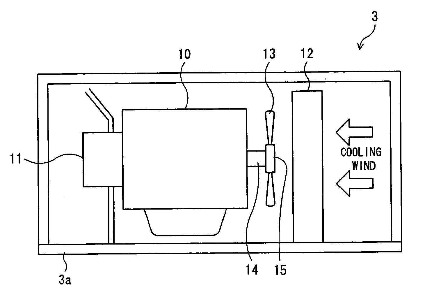
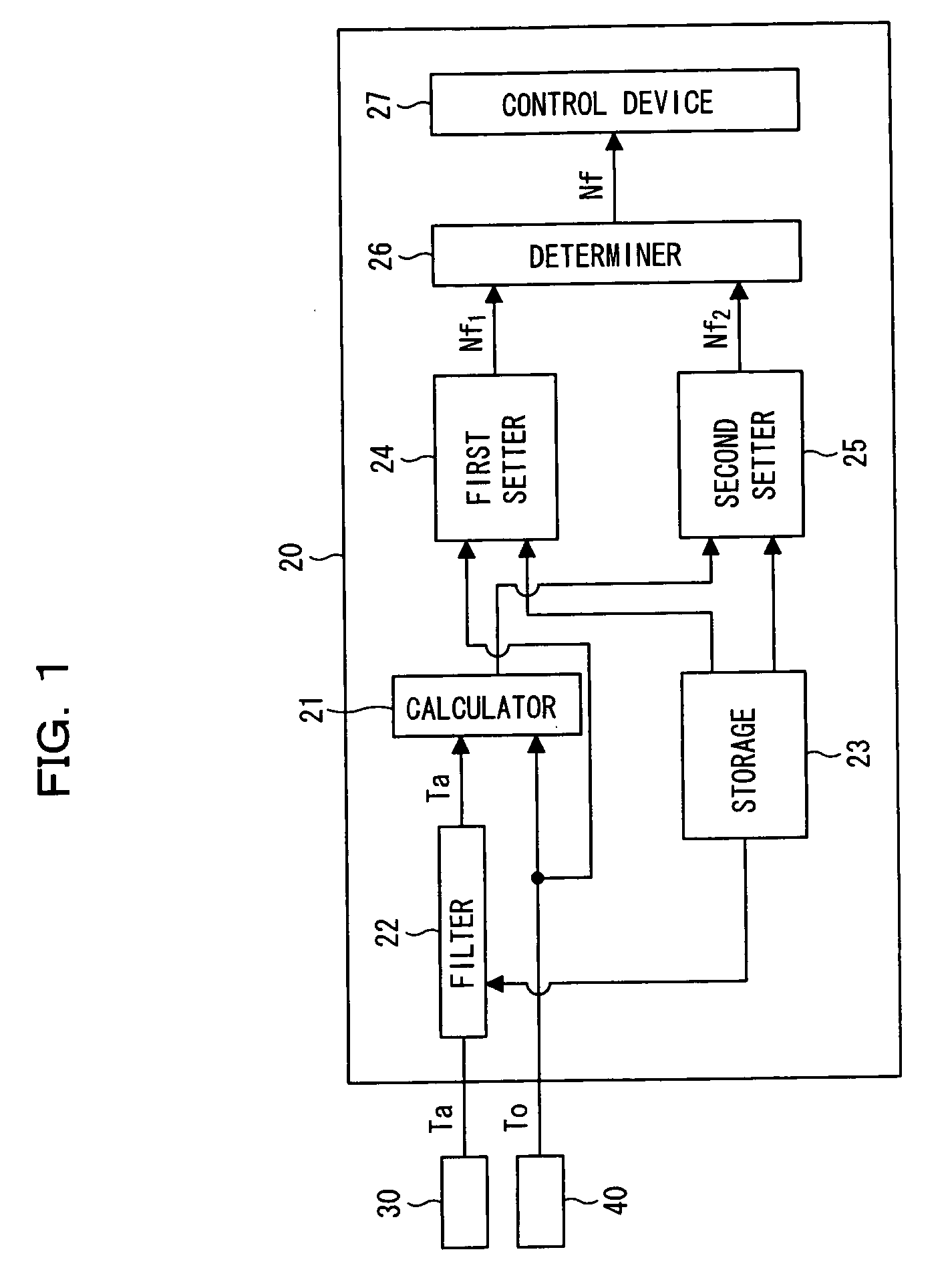
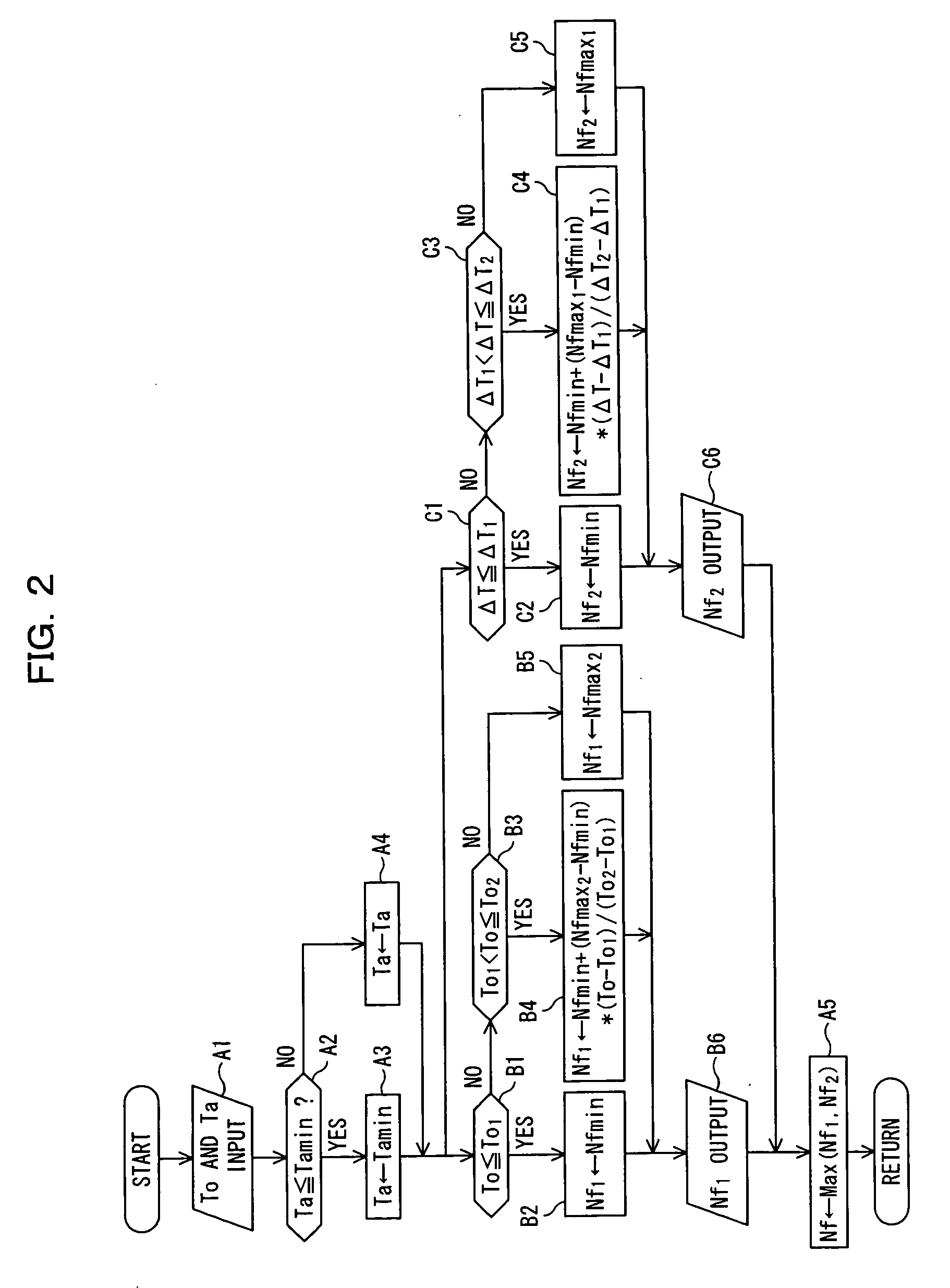
[0088]FIGS. 1 to 6 show a cooling fan controller in accordance with the preferred embodiment of the present invention. FIG. 1 is a block diagram showing the controller, FIG. 2 is a flowchart showing the contents of control which is performed by the controller, and FIGS. 3(a) and 3(b) are graphs showing the revolving speed (target revolving speed) of the cooling fan that is set by the controller, and FIG. 3(c) is a graph showing the revolving speed of the cooling fan that is set by a conventional cooling fan controller that employs only oil temperature information. FIGS. 4(a) to 4(c) are graphs showing the revolving speed of the cooling fan versus oil temperature, obtained by the experimental results controlled by the cooling fan controller and conventional controller, FIG. 4(a) showing at high-load, FIG. 4(b) showing at intermediate-lo...
PUM
 Abstract
Description
Claims
Application Information