Fuel injection controller for internal combustion engine

a technology for internal combustion engines and controllers, which is applied in the direction of electrical control, process and machine control, instruments, etc., can solve problems such as fuel pressure variations, and achieve the effect of high accuracy

Active Publication Date: 2009-03-05
DENSO CORP
View PDF5 Cites 24 Cited by
  • Summary
  • Abstract
  • Description
  • Claims
  • Application Information

AI Technical Summary

Benefits of technology

[0011]When the injecting of the fuel by the fuel injector and the pressure-feeding of the fuel by the fuel pump are performed at the same time, in the injection cylinder, the fuel pressure is varied by the effect of the injecting of the fuel and the pressure-feeding of the fuel, but in the non-injection cylinder, the fuel pressure is varied only by the effect of the pressure-feeding of the fuel (even if the injecting of

Problems solved by technology

However, in this case, when the fuel is pressure-fed to the accumulation container by the fuel pump, if the pressure-feeding of the fuel by the fuel pump and the injecting of the fuel

Method used


Image

  • Fuel injection controller for internal combustion engine
  • Fuel injection controller for internal combustion engine
  • Fuel injection controller for internal combustion engine

Examples


first embodiment

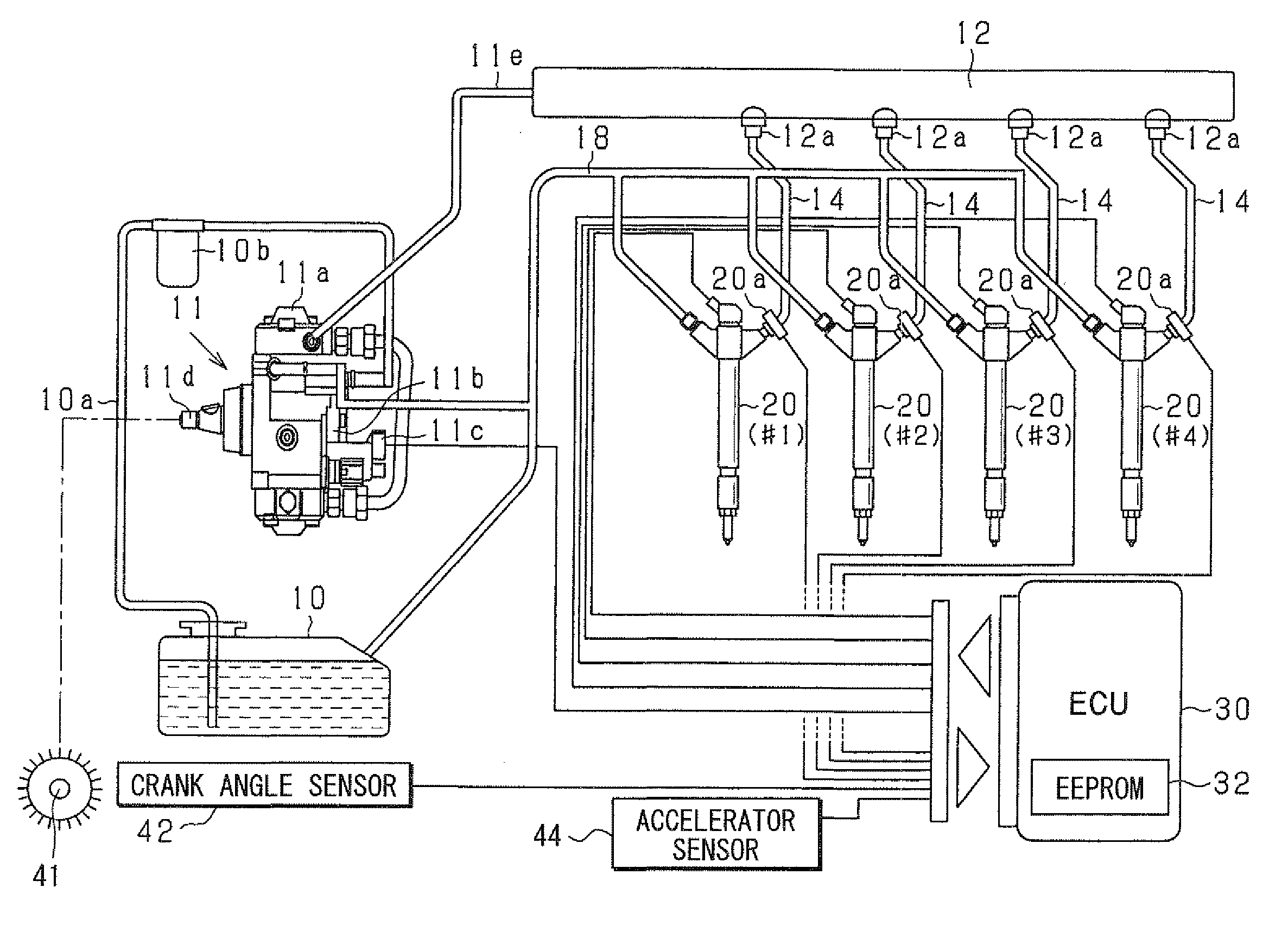
[0023]Hereinafter, a first embodiment that embodies the present invention will be described with reference to the drawings. An apparatus of this embodiment is mounted in, for example, a common rail type fuel injection system (system for supplying fuel injected at high pressure) in which a reciprocating diesel engine as an engine for an automobile is controlled. That is, this apparatus is used as an apparatus for injecting and supplying high-pressure fuel (for example, light oil having an injection pressure of about “1400 atm”) directly into the combustion chamber of a cylinder of a diesel engine (internal combustion engine).

[0024]The outline of the common rail type fuel injection system according to this embodiment will be described with reference to FIG. 1. A multi-cylinder engine (for example, 4 cylinder engine) for a 4-wheel automobile is assumed as the engine of this embodiment. In FIG. 1, respective injectors 20 are fitted in first to fourth cylinders (#1, #2, #3, and #4).

[0025...

second embodiment

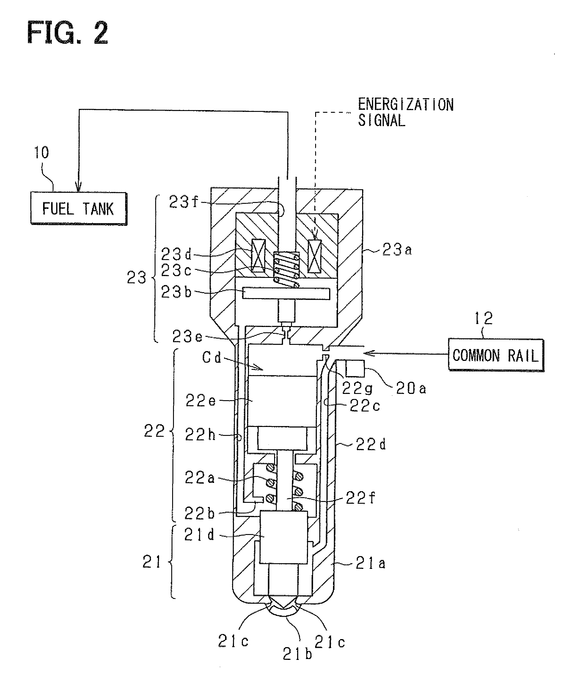
[0112]A second embodiment will be described hereinafter. The description of the portion that overlaps the first embodiment will be simplified and the different points between the two embodiments will be mainly described. The system configuration shown in FIG. 1 and the configuration of the injector 20 are the same as those shown in FIG. 2. The pressure sensor 20a is integrally fitted to the injector 20 and the fuel pressure is detected on the basis of the output of the pressure sensor 20a.

[0113]This embodiment employs the construction in which the injection characteristics by the injector 20 are computed on the basis of the pressure variation data that is the difference between the fuel pressure in the injection cylinder and the fuel pressure in the non-injection cylinder.

[0114]FIG. 10 is a flow chart showing the procedure of the processing of correcting the fuel pressure. This processing is performed by the ECU 30 in place of the above-mentioned processing shown in FIGS. 8A and 8B...


PUM


Abstract

A common rail type fuel injection system of an engine includes: a common rail for accumulating and holding high-pressure fuel; a fuel pump for pressure-feeding fuel to the common rail; and an injector for injecting the high-pressure fuel accumulated and held in the common rail. A pressure sensor is disposed in a fuel suction pod of the injector. An ECU sequentially detects a fuel pressure varied when the injector injects the fuel and sequentially detects a fuel pressure varied when the fuel pump pressure-feeds the fuel. When the injector injects the fuel the ECU computes injection pressure by the detection values of these pressures and computes injection characteristics by the injector on the basis of the injection pressure.

Description

CROSS-REFERENCE TO RELATED APPLICATION[0001]This application is based on Japanese Patent Application No. 2007-227120 filed on Aug. 31, 2007, the disclosure of which is incorporated herein by reference.FIELD OF THE INVENTION[0002]The present invention relates to a fuel injection controller for an internal combustion engine, which is applied to an accumulator type fuel injection system for performing fuel injection by use of high-pressure fuel accumulated in the accumulator of a common rail or the like.BACKGROUND OF THE INVENTION[0003]An apparatus described in JP-10-220272A (U.S. Pat. No. 6,142,121) is proposed as an apparatus of this kind, In a common rail type fuel injection system constructed of this fuel injection apparatus, fuel pressure-fed from a fuel pump is accumulated in a high-pressure state by a common rail. Then, the accumulated high-pressure fuel is supplied to the fuel injection valve of each cylinder through pipes (high-pressure fuel passage) disposed for each cylinder...

Claims


Application Information

Patent Timeline
IPC IPC(8): F02D41/30
CPCF02D41/2467F02D41/3845F02D41/40F02D41/402F02D2200/0602F02D2200/0604F02D2250/04F02D2250/14F02M57/005F02M2200/24Y02T10/40
Inventor NAKATA, KENICHIROISHIZUKA, KOJILI, RU-LONG
Owner DENSO CORP
Why Eureka
Try Eureka