Fuel injection characteristic sensing device and fuel injection command correcting device

a sensing device and fuel injection technology, applied in the direction of electrical control, process and machine control, instruments, etc., can solve the problem of difficulty in high-accuracy sensing of pressure fluctuation caused by the above-described injection

Active Publication Date: 2009-03-05
DENSO CORP
View PDF8 Cites 62 Cited by
  • Summary
  • Abstract
  • Description
  • Claims
  • Application Information

AI Technical Summary

Benefits of technology

[0059]Thus, the fuel injection command correcting device is constructed with the above-described fuel injection characteristic sensing device. Accordingly, for example, in the case where an error between the injection timing detected by the above-described fuel injection characteristic sensing device and a reference timing (an appropriate value beforehand obtained by the experiment and the like) is large, the error can be compensated by correcting the injection command to the injector such that an injection result during a present combustion cycle is reflected in an injection in a subsequent combustion cycle. By continuously performing the correction of the injection command while applying such the feedback to the injection command, the fuel injection at appropriate timing can be maintained over a long period of time.
[0060]Alternatively, the injection command to the injector may be corrected in one combustion cycle. Therefore, according to another aspect of the present invention, the correcting section uses a timing of a predetermined event concerning the fuel injection detected by the fuel injection characteristic sensing device in a certain combustion cycle of a target engine to correct the injection command to th

Problems solved by technology

Therefore, with such the device, it is difficult to sense the pressure

Method used


Image

  • Fuel injection characteristic sensing device and fuel injection command correcting device
  • Fuel injection characteristic sensing device and fuel injection command correcting device
  • Fuel injection characteristic sensing device and fuel injection command correcting device

Examples


Embodiment Construction

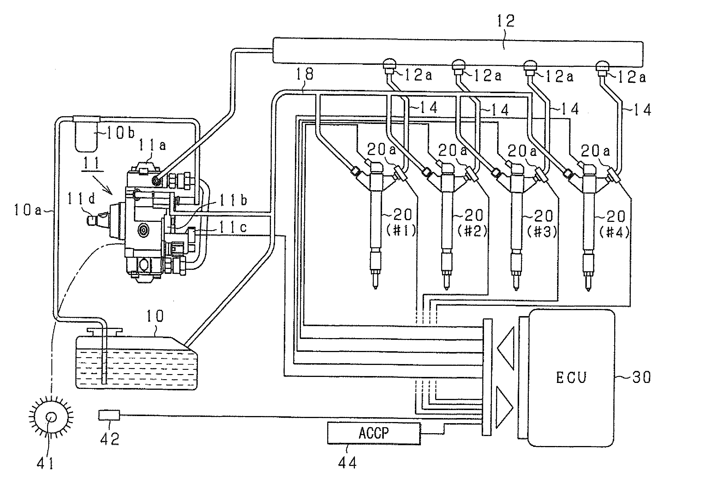
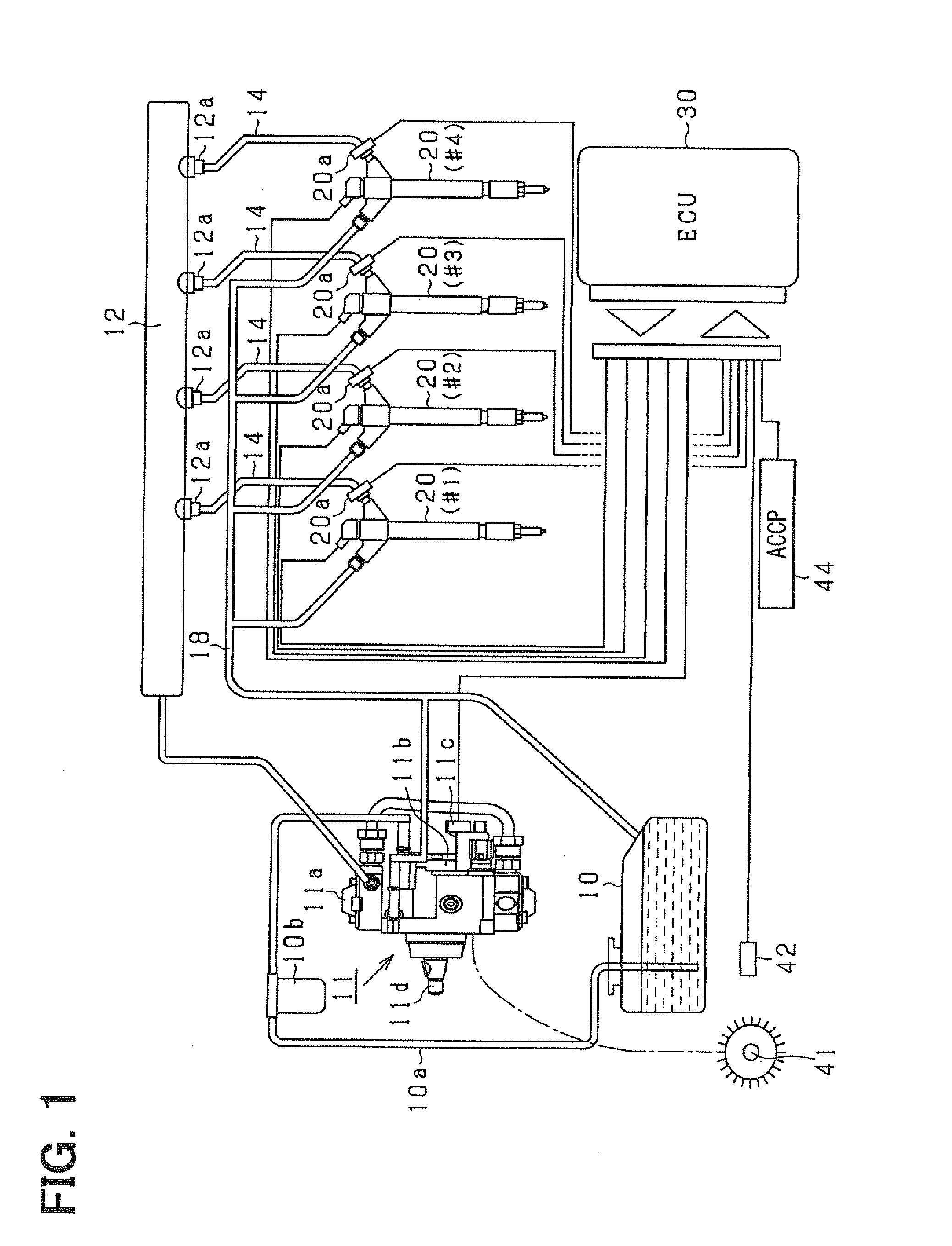
[0080]Hereafter, a fuel injection characteristic sensing device and a fuel injection command correcting device according to an embodiment of the present invention will be described with reference to the drawings. The devices according to the present embodiment are mounted, for example, in a common rail fuel injection system (high-pressure injection fuel supply system) for a diesel engine. That is, like the device described in Patent document 1, the devices according to the present embodiment are used for performing injection supply (direct injection supply) of high-pressure fuel (for example, light oil at injection pressure of 1000 atmospheres or higher) directly into a combustion chamber in a cylinder of a diesel engine.

[0081]First, an outline of the common rail fuel injection control system (an in-vehicle engine system) according to the present embodiment will be explained with reference to FIG. 1. It is assumed that the engine according to the present embodiment is a multi-cylind...


PUM


Abstract

A fuel injection characteristic sensing device obtains an injection characteristic of a target injector (an injector of each cylinder of a multi-cylinder engine) at each time. The device has a program for sequentially sensing fuel pressure at a sensing point corresponding to a fuel pressure sensor, which is provided at a fuel inlet of each injector, based on an output of the fuel pressure sensor. The device has a program for detecting predetermined timings (injection timings such as an injection start timing and an injection end timing) in a series of operations concerning fuel injection of the injector of each cylinder based on the sequentially sensed fuel pressure. Thus, the injection characteristic at each time including a temporal characteristic change can be obtained.

Description

CROSS REFERENCE TO RELATED APPLICATION[0001]This application is based on and incorporates herein by reference Japanese Patent Application No. 2007-227114 filed on Aug. 31, 2007.BACKGROUND OF THE INVENTION[0002]1. Field of the Invention[0003]The present invention relates to a fuel injection characteristic sensing device that senses a fuel injection characteristic at the time of performing injection supply of fuel to a target engine and to a fuel injection command correcting device that corrects an injection command to an injector based on the fuel injection characteristic sensing device.[0004]2. Description of Related Art[0005]As one of technologies for improving emission of an in-vehicle diesel engine or the like, there is a known technology (high-pressure injection) for injecting and supplying fuel, which is pressurized to high pressure, directly into a cylinder through an injector In recent years, a common rail fuel injection system (for example, a system described in Patent docum...

Claims


Application Information

Patent Timeline
IPC IPC(8): F02D41/00
CPCF02D41/3809F02D41/40F02D41/402Y02T10/44F02D2250/04F02M57/005F02M2200/24F02D2200/0604Y02T10/40
Inventor NAKATA, KENICHIROISHIZUKA, KOJILI, RU LONG
Owner DENSO CORP
Why Eureka
Try Eureka