

Level shift circuit
a level shift circuit and level shift technology, applied in logic circuits, pulse automatic control, pulse techniques, etc., can solve the problems of slow level shift, and large currents ib>1/b> and ib>2/b>, so as to reduce the layout of the level shift circuit, reduce the power consumption, and quick level shift circuit
- Summary
- Abstract
- Description
- Claims
- Application Information
AI Technical Summary
Benefits of technology
Problems solved by technology
Method used
Image

Examples
first embodiment
[0021]FIG. 3 shows a first embodiment according to the present invention, in which a level shift circuit 30 includes an input stage 32 and an output stage 34 coupled together by nodes N1 and N2. The high level and low level of the input signal VIN are voltages VP1 and VS1, respectively, and after level shift, the high level and low level of the output signal VOUT are voltages VP2 and VS2, respectively. The input stage 32 has PMOS transistors M1, M2, M3 and M4, NMOS transistors M5 and M6, and a current control circuit 36 configured to change the voltages on the nodes N1 and N2 according to the input signal VIN. The transistor M1 is configured as a diode connected in parallel with the transistor M2 between a voltage source VP2 and the node N1, and the transistor M4 is configured as another diode connected in parallel with the transistor M3 between the voltage source VP2 and the node N2. The transistor M5 is connected between the node N1 and the current control circuit 36 and is contro...
second embodiment
[0026]FIG. 4 shows a second embodiment according to the present invention, in which a level shift circuit 40 includes an input stage 42 and an output stage 34 coupled to each other by nodes N1 and N2. The input stage 42 has transistors M1, M2, M3, M4, M5 and M6, and a current control circuit 44 configured to change the voltages on the nodes N1 and N2 according to an input signal VIN. In the current control circuit 44, a capacitor C1 is connected between the transistor M5 and a voltage source VS1, a capacitor C2 is connected between the transistor M6 and the voltage source VS1, and resistors R1 and R2 are connected in parallel with the capacitors C1 and C2, respectively. Similarly, during the transition state, since the current I1 or I2 flowing through the transistor M5 or M6 is large, the node N1 or N2 is discharged with high speed for quick level shift. In the steady state, when the capacitors C1 and C2 are fully charged by the currents I1 and 12, the resistors R1 and R2 will limit...
third embodiment
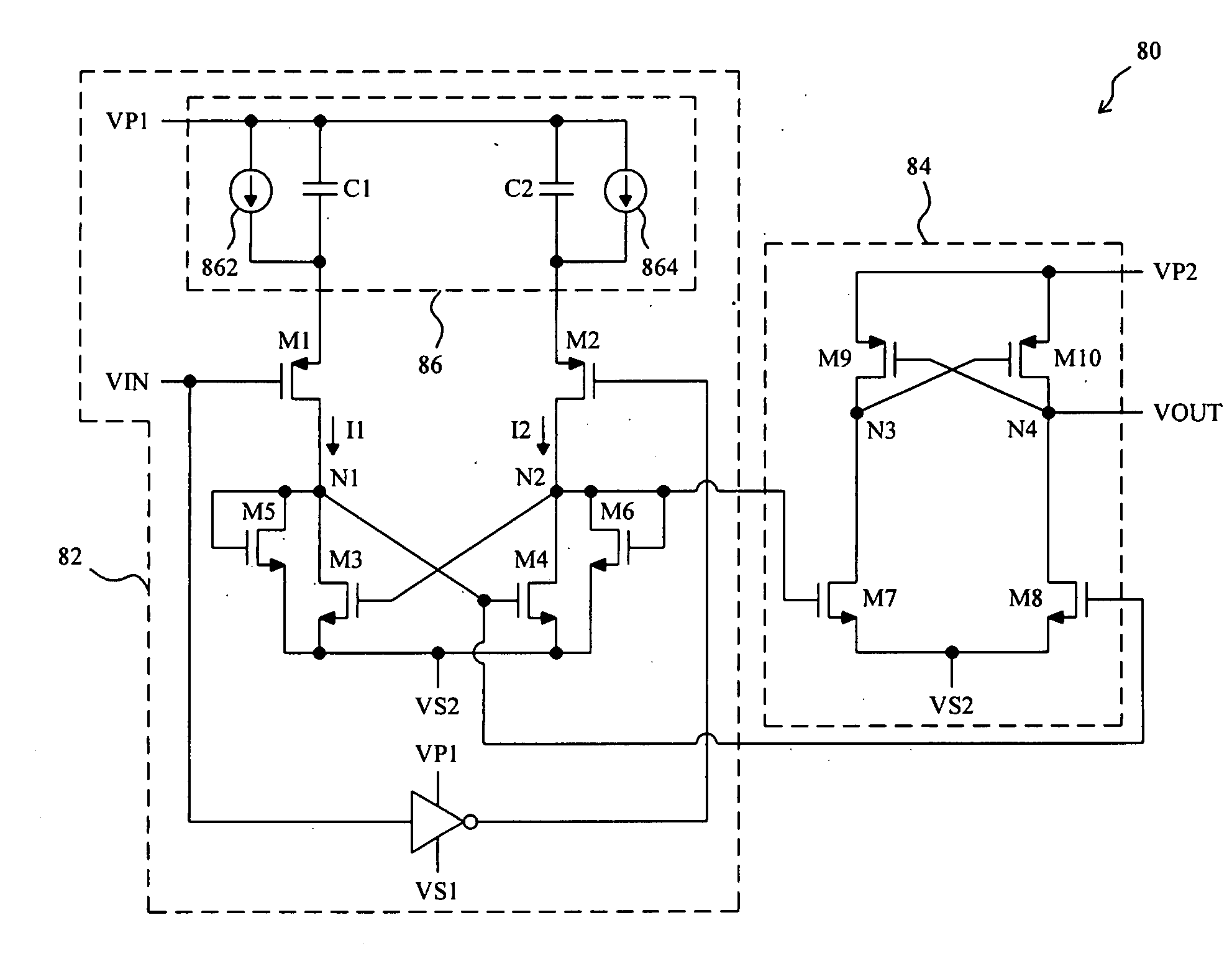
[0027]In the third embodiment shown in FIG. 5, a level shift circuit 50 includes an input stage 52 and an output stage 34 coupled together by nodes N1 and N2. The input stage 52 has transistors M1, M2, M3, M4, M5 and M6, and a current control circuit 54 configured to change the voltages on the nodes N1 and N2 according to an input signal VIN. In the current control circuit 54, a capacitor C1 is connected between the transistor M5 and a voltage source VS1, a capacitor C2 is connected between the transistor M6 and the voltage source VS1, small current sources 542 and 544 are connected in parallel with the capacitors C1 and C2, respectively, and transistors M11 and M12 functioning as switches controlled by the input signal VIN are connected in parallel with the capacitors C1 and C2, respectively. When the input signal VIN transits to a low level, the transistor M5 is turned off and the transistor M6 is turned on, thereby turning on a large current I2 flows through the transistor M6 to ...
PUM
 Abstract
Description
Claims
Application Information