High powered inductors using a magnetic basis

a high-power inductors and magnetic base technology, applied in the direction of magnets, magnetic bodies, cores/yokes, etc., can solve the problems of limiting the production of high-frequency core losses, the inherent limitation of magnetic saturation at relatively low current levels, etc., to achieve high saturation current performance, reduce core losses, and adjust inductance characteristics

Inactive Publication Date: 2009-03-12
VISHAY DALE ELECTRONICS INC
View PDF13 Cites 13 Cited by
  • Summary
  • Abstract
  • Description
  • Claims
  • Application Information

AI Technical Summary

Benefits of technology

[0005]It is a further object, feature, or advantage of the present invention to provide an inductor which has lower core losses at high ripple currents (>5 A) and frequencies (>200 kHz) in a thin package yet also have the high saturation current performance of powdered iron.
[0006]Another object, feature, or advantage of the present invention is to use adhesive film thickness or magnet particle size to adjust inductance characteristics.
[0007]A further object, feature, or advantage of the present invention is to increase the capability of an inductor to effectively handle more DC while maintaining inductance.
[0008]One or more of these and / or other objects, features, or advantages of the present invention will become apparent from the description of the invention that follows.
[0009]According to one aspect of the present invention, a biased gap inductor includes a first ferromagnetic plate, a second ferromagnetic plate, a conductor sandwiched between the first ferromagnetic plate and the second ferromagnetic plate, and an adhesive between the first ferromagnetic plate and the second ferromagnetic plate, the adhesive comprising magnetically hard magnet powder to thereby form at least one magnetic gap. The adhesive has a thickness of less than 500 um and preferably less than 100 um. The magnetic powder size can be used to set the inductance level of the part. Also the amount of magnet powder can modify characteristics of the part to produce a desired performance.
[0010]According to another aspect of the present invention, a method of forming an inductor includes providing a first ferromagnetic plate and a second ferromagnetic plate and a conductor, placing the conductor between the first ferromagnetic plate and the second ferromagnetic plate, adhering the first ferromagnetic plate to the second ferromagnetic plate with a composition comprising an adhesive and a magnet powder to form magnetic gaps, and magnetizing the inductor. The composition has a thickness of less than 500 um and preferably less than 100 um.

Problems solved by technology

Ferrite based low profile inductors have an inherent limitation of magnetic saturation at relatively low levels of current.
Pressed iron inductors allow for much higher input current than ferrite inductors, but have the limitation of producing high core losses at high frequencies (such as frequencies greater than 200 kHz).

Method used


Image

  • High powered inductors using a magnetic basis
  • High powered inductors using a magnetic basis
  • High powered inductors using a magnetic basis

Examples


Embodiment Construction

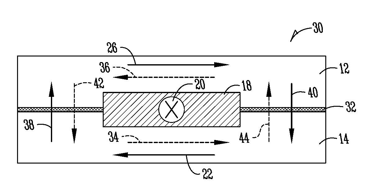
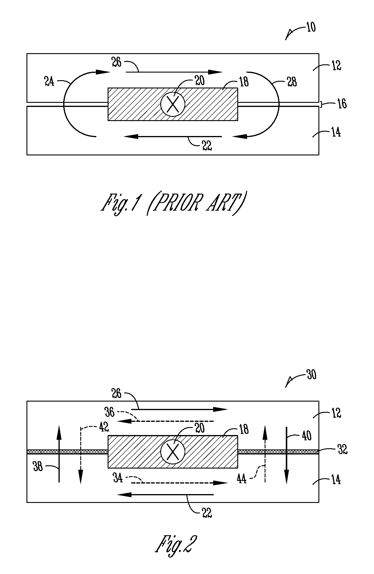
[0017]FIG. 1 illustrates a prior art device where a single strip of copper can be placed between two ferrite parts to create an inductor. While this is effective in creating low value, high frequency inductors, it limits the amount of input current the inductor can handle without saturating. The primary cause of saturation comes from the fact that all magnetic flux induced by the copper flows through narrow cross-sectional areas. FIG. 1 illustrates the flux pattern in a single copper strip inductor. In FIG. 1, an inductor 10 has a first ferromagnetic plate 12 and a second ferromagnetic plate 14. There is a spacing 16 between the first ferromagnetic plate 12 and the second ferromagnetic plate 14. The magnetic flux induced by a current through the single strip copper conductor 18 is split between each plate 12, 14. Input current 20 is shown using notation to indicate that the current is flowing into the page. Arrows 22, 24, 26, 28 indicate the direction of magnetic flux induced by the...


PUM

PropertyMeasurementUnit
thicknessaaaaaaaaaa
thicknessaaaaaaaaaa
frequenciesaaaaaaaaaa

Abstract

A biased gap inductor includes a first ferromagnetic plate, a second ferromagnetic plate, a conductor sandwiched between the first ferromagnetic plate and the second ferromagnetic plate, and an adhesive between the first ferromagnetic plate and the second ferromagnetic plate, the adhesive comprising magnet powder to thereby form at least one magnetic gap. A method of forming an inductor includes providing a first ferromagnetic plate and a second ferromagnetic plate and a conductor, placing the conductor between the first ferromagnetic plate and the second ferromagnetic plate, adhering the first ferromagnetic plate to the second ferromagnetic plate with a composition comprising an adhesive and a magnet powder to form magnetic gaps, and magnetizing the inductor.

Description

CROSS-REFERENCE TO RELATED APPLICATIONS[0001]This application claims priority under 35 U.S.C. §119 to provisional application Ser. No. 60 / 970,578 filed Sep. 7, 2007, herein incorporated by reference in its entirety.BACKGROUND OF THE INVENTION[0002]Low profile inductors, commonly defined as inductors having a profile less than about 10 mm are in existence today in the form of ferrites with unique geometries and pressed iron powder around a wound coil. Ferrite based low profile inductors have an inherent limitation of magnetic saturation at relatively low levels of current. When magnetic saturation occurs, inductance value decreases dramatically.[0003]Pressed iron inductors allow for much higher input current than ferrite inductors, but have the limitation of producing high core losses at high frequencies (such as frequencies greater than 200 kHz). What is needed is an efficient means to provide inductance at high frequencies allowing high input currents.[0004]It is therefore a primar...

Claims


Application Information

Patent Timeline
Patent Type & Authority Applications(United States)
IPC IPC(8): H01F27/02H01F7/06
CPCH01F3/14Y10T29/49073H01F27/2847H01F17/043
Inventor HANSEN, THOMAS T.
Owner VISHAY DALE ELECTRONICS INC
Why Eureka
Try Eureka