Flux channeled, high current inductor

a high-current inductors and channel technology, applied in the direction of transformers/inductance details, inductances with magnetic cores, inductances, etc., can solve the problems of limiting the production of high core losses at high frequencies, inherent limitations of magnetic saturation at relatively low current levels, etc., to achieve low core losses, adjust inductance characteristics, and high saturation current performance

Inactive Publication Date: 2011-01-04
VISHAY DALE ELECTRONICS INC
View PDF9 Cites 6 Cited by
  • Summary
  • Abstract
  • Description
  • Claims
  • Application Information

AI Technical Summary

Benefits of technology

[0003]It is therefore a primary, object, feature, or advantage of the present invention to improve upon the state of the art.
[0004]It is a further object, feature, or advantage of the present invention to provide an inductor which has lower core losses at high ripple currents (>5 A) and frequencies (>100 kHz) in a thin package yet also have the high saturation current performance of powdered iron.
[0005]Another object, feature, or advantage of the present invention is to use adhesive film thickness to adjust inductance characteristics.
[0006]Yet another object, feature, or advantage of the present invention is to utilize a split conductor geometry that divides magnetic flux thus reducing flux density in thin sections of the magnetic material.
[0007]A further object, feature, or advantage of the present invention is to employ a layer of high saturating magnetic material to channel DC induced flux from the layer of low saturating magnetic material increasing inductance and saturation current capability and thereby also providing lower high frequency losses by using the low saturating ferrite material.
[0008]Another object, feature, or advantage of the present invention is to use a thin adhesive film to set inductance level of the part and join the ferromagnetic plates together.

Problems solved by technology

Ferrite based low profile inductors have an inherent limitation of magnetic saturation at relatively low levels of current.
Pressed iron inductors allow for much higher input current than ferrite inductors, but have the limitation of producing high core losses at high frequencies (such as frequencies greater than 100 kHz).

Method used


Image

  • Flux channeled, high current inductor
  • Flux channeled, high current inductor
  • Flux channeled, high current inductor

Examples


Embodiment Construction

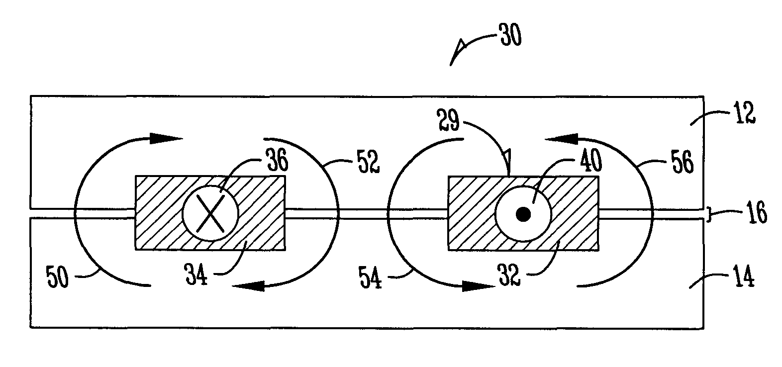
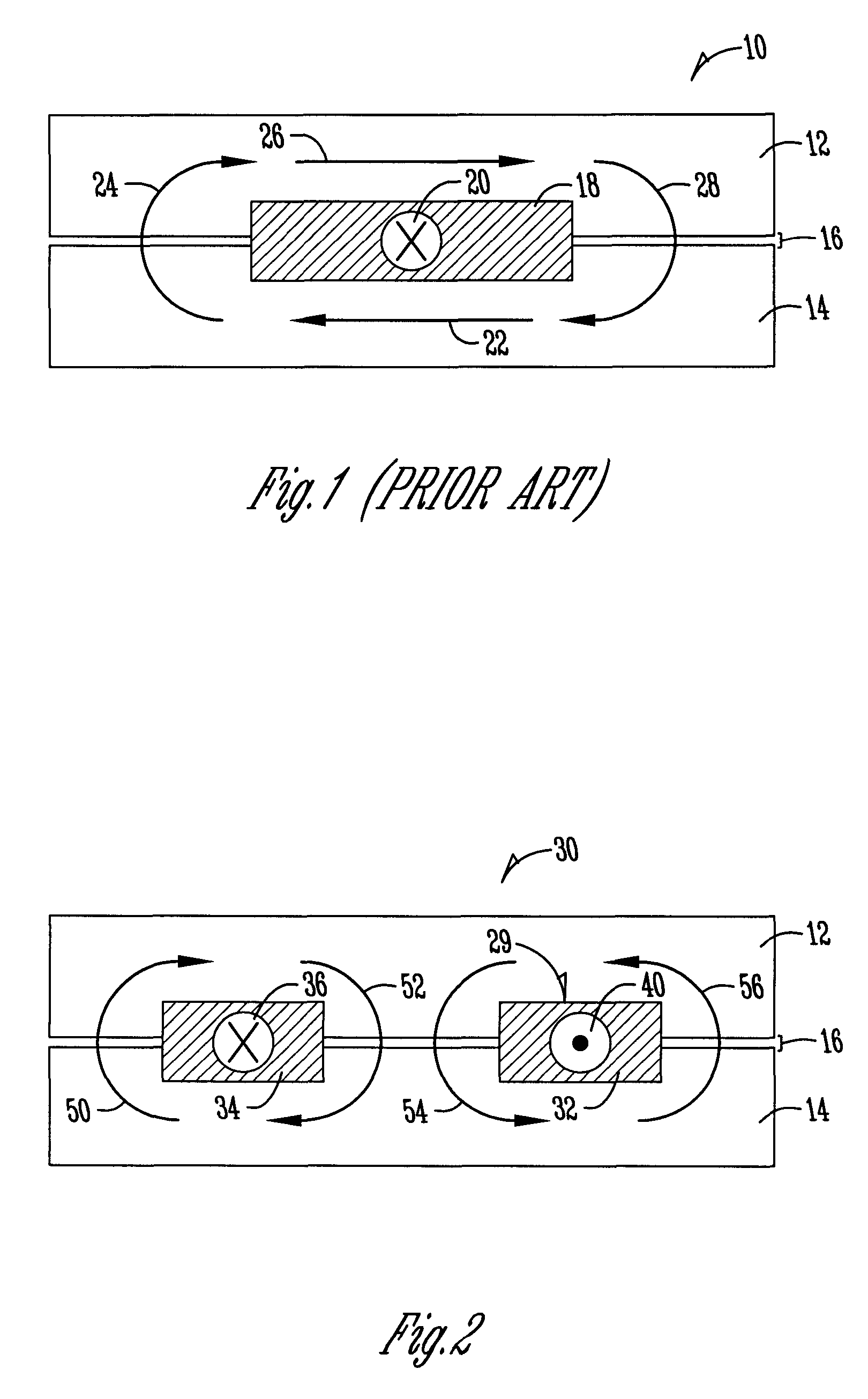
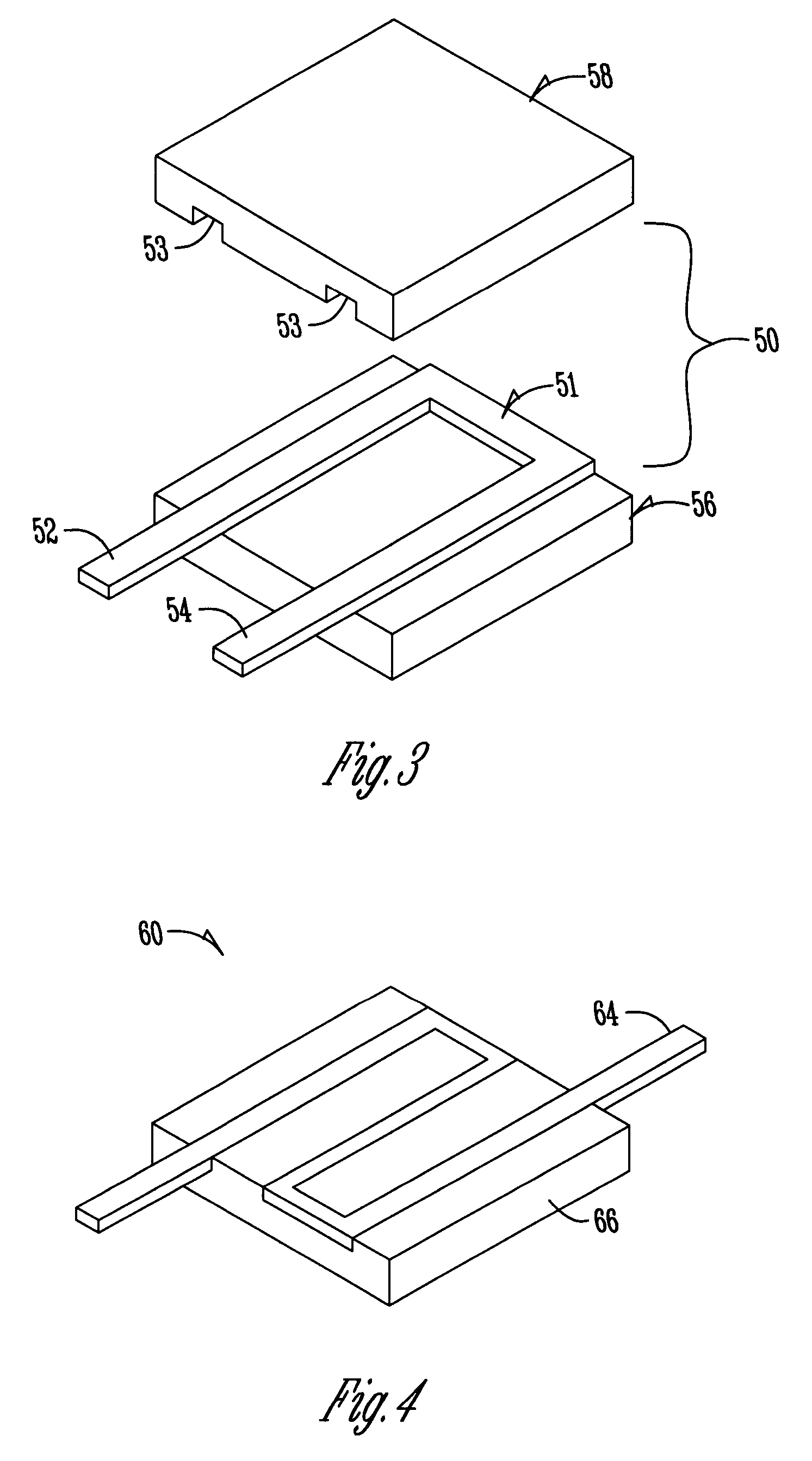
[0037]The present invention includes an efficient, low profile, high current inductor. In one embodiment of the present invention, two ferromagnetic plates are spaced by a thin adhesive film. The adhesive film is preferably comprised of a layer of solid B staged epoxy manufactured to a tightly controlled thickness. Alternate forms of thin adhesive films have solid reinforcements such as glass fiber or KAPTON (polyimide) tape. The use of the adhesive film has a dual role in the effectiveness of the component. Adhesive thickness is selected to raise or lower the inductance of the part. Small adhesive film thickness creates an inductor with a high inductance level. A thick adhesive film reduces the inductance of the part and increases magnetic saturation resistance to high input current. Thus, the adhesive film thickness can be selected to tailor the inductance of the part for a specific application. The second role of the adhesive is to permanently bind the parts together thereby maki...


PUM

PropertyMeasurementUnit
frequenciesaaaaaaaaaa
saturation current performanceaaaaaaaaaa

Abstract

A flux-channeled high current inductor includes an inductor body having a first end and an opposite second end and a conductor extending through the inductor body. The conductor includes a plurality of separate channels through a cross-sectional area of the inductor body thereby directing magnetic flux inducted by a current flowing through the conductor into two or more cross-sectional areas and reducing flux density of a given single area. The inductor body may be formed of a first ferromagnetic plate and a second ferromagnetic plate. The inductor may be formed from a single component magnetic core and have one or more slits to define inductance. The inductor may be formed of a magnetic powder. A method is provided for manufacturing flux-channeled high current inductors.

Description

BACKGROUND OF THE INVENTION[0001]Low profile inductors, commonly defined as inductors having a profile less than about 10 mm are in existence today in the form of ferrites with unique geometries and pressed iron powder around a wound coil. Ferrite based low profile inductors have an inherent limitation of magnetic saturation at relatively low levels of current. When magnetic saturation occurs, inductance value decreases dramatically.[0002]Pressed iron inductors allow for much higher input current than ferrite inductors, but have the limitation of producing high core losses at high frequencies (such as frequencies greater than 100 kHz). What is needed is an efficient means to provide inductance at high frequencies allowing high input currents.BRIEF SUMMARY OF THE INVENTION[0003]It is therefore a primary, object, feature, or advantage of the present invention to improve upon the state of the art.[0004]It is a further object, feature, or advantage of the present invention to provide an...

Claims


Application Information

Patent Timeline
Patent Type & Authority Patents(United States)
IPC IPC(8): H01F5/00
CPCH01F17/06H01F27/255H01F3/10H01F3/14H01F27/292H01F17/043
Inventor HANSEN, THOMAS T.HOFFMAN, JEROME J.
Owner VISHAY DALE ELECTRONICS INC
Why Eureka
Try Eureka