This helps you quickly interpret patents by identifying the three key elements:
Problems solved by technology
Method used
Benefits of technology
Benefits of technology
[0024]Thus, the primary object of the present invention is to solve the above described problems to make it possible to provide a high speed liquid ejecting head which is significantly higher in nozzle response, being therefore significantly higher in recording speed and image quality than a high speed liquid ejecting head in accordance with the prior art.
[0026]According to the present invention, the first nozzle is in connection to the common ink supply chamber, and extends in the direction perpendicular to the liquid ejecting direction, whereas the second nozzle is extended in the direction parallel to the ink ejecting direction, making it possible to dispose multiple nozzles at a significantly higher level of density than the level of density at which nozzles are disposed in a comparable ink jet recording head in accordance with the prior art, without reducing the ink jet recording head in nozzle response. Therefore, the present invention can significantly increase an ink jet recording head (apparatus) in recording speed, compared to a comparable ink jet recording head in accordance with the prior art.
Problems solved by technology
On the other hand, this ink ejecting method suffers from problems peculiar thereto.
One of them is that the heat generated by an electrothermal transducer accumulates in a recording head, which results in the change in the volume of the ink droplet which an ink jet recording head jets.
Another problem is that the electrothermal transducer is affected by the impact attributable to the collapsing of a bubble; the electrothermal transducer suffers from cavitation.
Further, this ink ejecting method is problematic in that the air having dissolved into ink would reappear, as air bubbles, in the recording head, affecting thereby the ink jet recording head in terms of ink ejecting performance and image quality.
Thus, it reduces the nozzle 105b in response speed, making it difficult to increase the ink jet recording head in recording speed.
However, this solution has its own problem.
That is, they cause the ink jet recording head to change in the shape in which the ink jet recording head jets ink droplets, causing thereby such a problem as the increase in the number by which satellite ink droplets are produced.
Method used
Image
Click on the blue label to locate the original text in one second.
Reading with bidirectional positioning of images and text.
Examples
embodiment 1
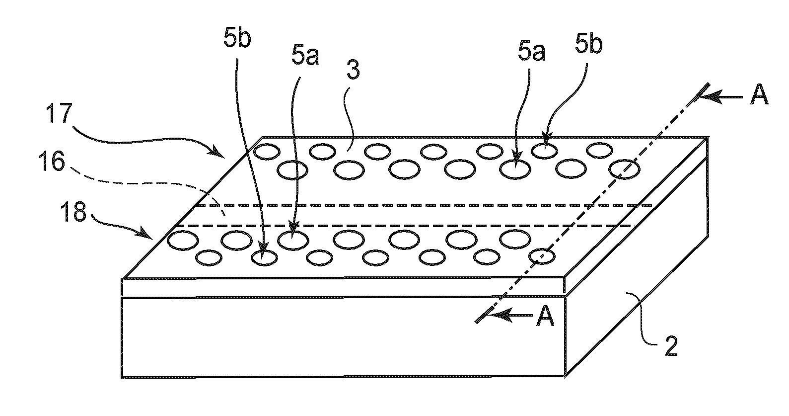
[0064]FIG. 5(a) is a schematic drawing of the wiring on the substrate 2 of ink jet recording head chip. FIG. 5(b) is a schematic drawing of the wiring on the substrate 2, which is different in position, in terms of the thickness direction of the substrate 2, from the wiring shown in FIG. 5(a) (wiring on back side of substrate 2 from wiring shown in FIG. 5(a)). The common wiring 25 shown in FIG. 5(a) is in electrical connection to the dedicated wiring26, shown in FIG. 5(b), which is different in position from the common wiring 25 in terms of the thickness direction of the substrate 2, through the contact hole 27 (through hole) shown in FIG. 5(a).
[0065]In this embodiment, the first nozzle column 17 is on one side of the long and narrow common ink supply chamber 16, in terms of the direction parallel to the shorter edges of the common ink supply chamber 16, and the second nozzle column 18 is on the other side. Referring to FIG. 4(a), the ink ejection outlets 14a and 14b of the nozzle c...
embodiment 2
[0072]FIG. 6 is a phantom plan view of a part of the ink jet recording head in the second embodiment of the present invention, as seen from the direction perpendicular to the top surface of the ink passage plate 3, and shows the nozzle structure of the recording head. Next, referring to FIG. 6, the specific differences of the ink jet recording head in this embodiment from the ink jet recording head in the first embodiment will be described.
[0073]Referring to FIG. 6, in this embodiment, the centerline of the dedicated ink passage 19a of the first nozzle 5a is offset from the center of the primary surface of the heater 11, in terms of the direction parallel to the nozzle columns. Positioning the dedicated ink passage 19a of the first nozzle 5a as shown in FIG. 6 relative to the heater 11 causes ink to circularly flow about the axial line of the ink ejection outlet 14, as disclosed in Japanese Laid-open Patent Application 2002-321369. That is, with the ink jet recording head structured...
embodiment 3
[0074]FIG. 7 shows the nozzle structure of the ink jet recording head in the third embodiment. FIG. 7(a) is a phantom plan view of a part of the ink jet recording head, as seen from the direction perpendicular to the primary surface of the ink passage plate 3. FIG. 7(b) is a sectional view of the part of the ink jet recording head shown in FIG. 7(a), at a plane C-C shown in FIG. 7(a). Next, referring to FIG. 7, the specific differences of the ink jet recording head in this embodiment from the ink jet recording head in the first embodiment will be described.
[0075]Referring to FIG. 7, the ink jet recording head in this embodiment is structured so that the positional relationship between the heater 11 of the second nozzle 5b and the first nozzle 5a, positional relationship between ink ejection outlet 14b the second nozzle 5b and the first nozzle 5a, and positional relationship between the dedicated ink passages 19b of the second nozzle 5b and the first nozzle 5a, are reverse to those i...
PUM
Abstract
A liquid ejecting head includes a plurality of nozzles each including an ejection outlet for ejecting a droplet, an ejection energy generating element, disposed at a position opposing the ejection outlet, for generating energy for ejecting a droplet, a pressure chamber provided with the ejection energy generating element and fluidly communicating with the ejection outlet, and a supply passage for supplying the liquid to the pressure chamber, wherein the nozzles include a first nozzle and a second nozzle which are connected with respective ones of the supply passages having lengths different from each other, wherein the first nozzle and the second nozzle are, disposed at one end portion with respect to a widthwise direction of an elongated supply chamber for supplying the liquid to the first nozzle, wherein the supply passage for the first nozzle extends in a direction perpendicular to a direction of liquid ejection from the ejection outlet and fluidly communicates with the supply chamber, and wherein the supply passage for the first nozzle extends in a direction parallel with the direction of liquid ejection.
Description
FIELD OF THE INVENTION AND RELATED ART[0001]The present invention relates to a liquid jet head for jet liquid such as ink.[0002]In recent years, demand has been increasing for a recording apparatus which is significantly higher in speed, resolution, and image quality, and also, lower in noise than a conventional recording apparatus. One of the recording apparatuses which can satisfy such demand is an ink jet recording apparatus. An ink jet recording apparatus is structured to record an image on recording paper by jet droplets of ink (recording liquid) from its recording head so that the droplets of ink fly to the recording paper and adhere to the surface of the recording paper.[0003]Generally, an ink jet recording apparatus employs energy generating elements as the means for jet droplets of ink. Among various energy generating elements usable as the means for ejecting droplets of ink, an electrothermal transducer, such as a heater, and an electromechanical transducer, such as piezoe...
Claims
Application Information
Patent Timeline
Application Date:The date an application was filed.
Publication Date:The date a patent or application was officially published.
First Publication Date:The earliest publication date of a patent with the same application number.
Issue Date:Publication date of the patent grant document.
PCT Entry Date:The Entry date of PCT National Phase.
Estimated Expiry Date:The statutory expiry date of a patent right according to the Patent Law, and it is the longest term of protection that the patent right can achieve without the termination of the patent right due to other reasons(Term extension factor has been taken into account ).
Invalid Date:Actual expiry date is based on effective date or publication date of legal transaction data of invalid patent.

