
Method and system for evaluating an object that has a repetitive pattern

a technology of repetitive pattern and object evaluation, applied in the direction of material analysis through optical means, measurement devices, instruments, etc., can solve the problems of different detection signals, weak amplitude image electric field, and inability to detect different signals

Active Publication Date: 2009-03-12
APPL MATERIALS ISRAEL LTD
View PDF16 Cites 13 Cited by
  • Summary
  • Abstract
  • Description
  • Claims
  • Application Information

AI Technical Summary

Problems solved by technology

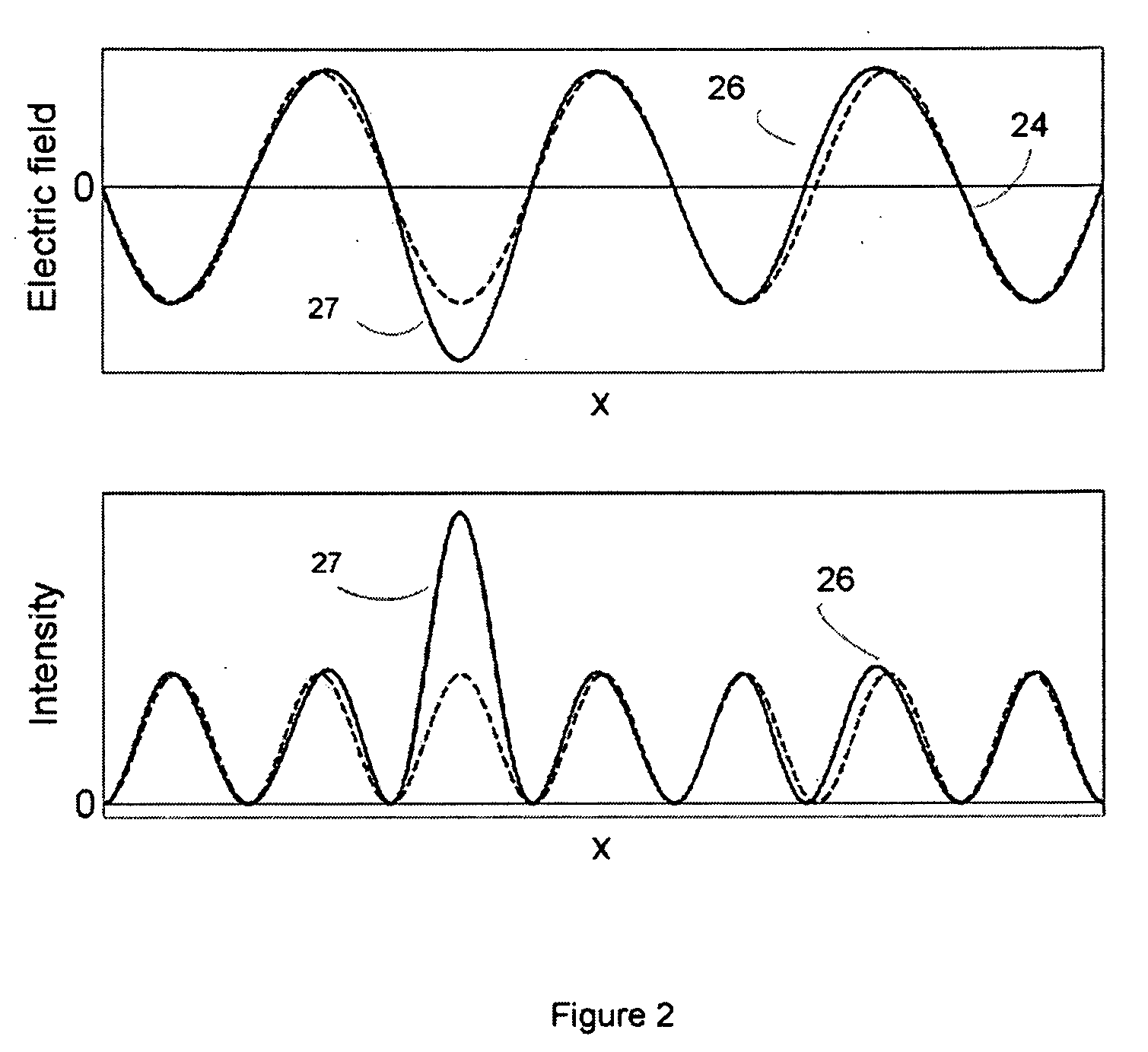
Defect information representative of defects that appear over regions of the pattern that give rise to low-amplitude image electric field may typically be substantially weaker (and even unnoticeable) in relation to defects that appear over regions of the pattern where the resulting image electric field has a substantial amplitude.
It is noted that in general, similar defects that are located within different backgrounds can result in different detection signals.

Method used


Image

  • Method and system for evaluating an object that has a repetitive pattern
  • Method and system for evaluating an object that has a repetitive pattern
  • Method and system for evaluating an object that has a repetitive pattern

Examples


Embodiment Construction

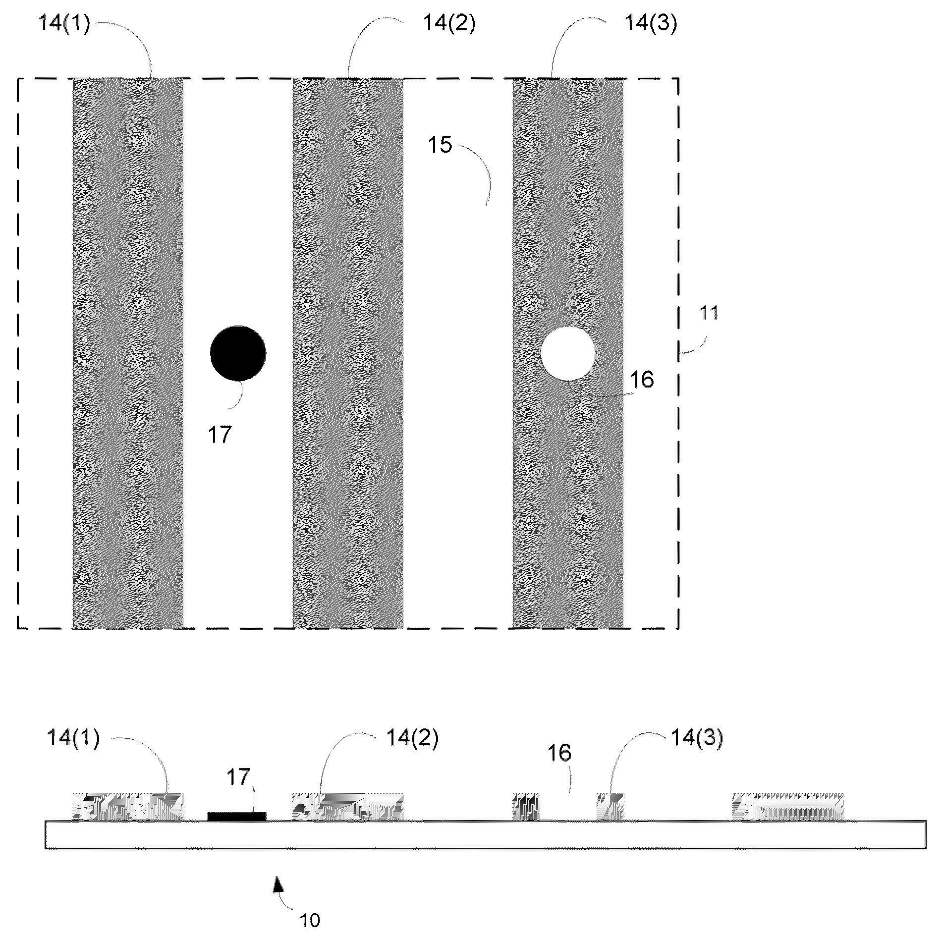
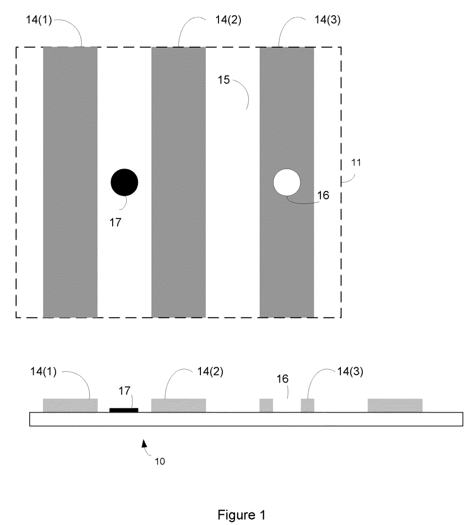
[0042]A method and a system for evaluating an object that includes a repetitive pattern are provided. It is noted that the system (or method) can apply transmissive inspection schemes, reflective inspections schemes, can use a pulsed light source or a continuous light source, can utilize visible light, utilize ultraviolet light or utilize deep ultraviolet light, can utilize on-axis illumination, off-axis illumination, can include multiple detectors, can include one or more spatial filters or apertures, can perform defect detection, defect review, metrology, and the like.

[0043]For simplicity of explanation the following figures refer to an inspection of a mask by applying a transmissive inspection scheme. It is noted that other objects (such as but not limited to wafers) can be inspected. It is noted that even a mask can be inspected in a reflective mode.

[0044]Those of skill in the art sill appreciate that the intensity of a detection signal is proportional to the squared absolute (c...


PUM


Abstract

A method and system for evaluating an object that has a repetitive pattern. Illumination optics of an optical unit are adapted to scan a spot of radiation over a repetitive pattern that includes multiple regularly repeating structural elements that are optically distinguishable from their background, generating a diffraction pattern that includes multiple diffraction lobes. Collection optics are adapted to focus radiation from the repetitive pattern onto a detector. The focused radiation includes a single diffraction lobe while not including other diffraction lobes. A grey field detector generates detection signals, responsive to the focused collected radiation. The optical unit is adapted to maintain, at a detection surface of the grew field detector, a radiation pattern that includes a first radiation pattern component resulting from the repetitive pattern and a second radiation pattern component resulting from a defect; wherein the first radiation pattern component is stronger than the second radiation component.

Description

RELATED APPLICATIONS[0001]This application is a NONPROVISIONAL of, claims priority to and incorporates by reference U.S. Provisional Patent Application No. 60 / 949,461, filed Jul. 12, 2007.FIELD OF THE INVENTION[0002]This invention is generally in the field of automatic optical evaluation of objects such as masks or wafers that include a repetitive pattern.BACKGROUND OF THE INVENTION[0003]Objects such as wafers and photomasks are evaluated by illuminating the object by radiation and detecting signals that are scattered from the object, are reflected from the object or pass through the object. The radiation can include light radiation, ultra violet radiation and deep ultra violet radiation.[0004]The detected signals are processed by one of few well known defect detection algorithms. Some of the algorithms include comparing detection signals that represent an inspected pattern to corresponding signals that represent a reference pattern. The latter may be for example a corresponding sim...

Claims


Application Information

Patent Timeline
IPC IPC(8): G01N21/88
CPCG01N21/95623H01L22/00
Inventor MANGAN, SHMUELSAGIV, AMIR MOSHE
Owner APPL MATERIALS ISRAEL LTD
Learn More