Light guide with imprinted phosphor

a technology of imprinted phosphor and light guide, which is applied in the field of backlights, can solve the problems of phosphorescent or fluorescent materials, hot spots, undesirable stray light, etc., and achieve the effect of reducing costs

Inactive Publication Date: 2009-03-12
WORLD PROPERTIES
View PDF21 Cites 79 Cited by
  • Summary
  • Abstract
  • Description
  • Claims
  • Application Information

AI Technical Summary

Benefits of technology

[0016]A further object of the invention is to provide a light guide t

Problems solved by technology

A dye simply absorbs light and, although useful, is generally not as desirable as phosphorescent or fluorescent materials.
Even so, there can be problems with “hot spots” (glare); for example, where light is coupled to the light guide from a source.
At the edges of a light guide, some of the light does not enter the light guide at an angle necessary for total internal reflection, producing undesirable stray light.
S

Method used


Image

  • Light guide with imprinted phosphor
  • Light guide with imprinted phosphor
  • Light guide with imprinted phosphor

Examples


Embodiment Construction

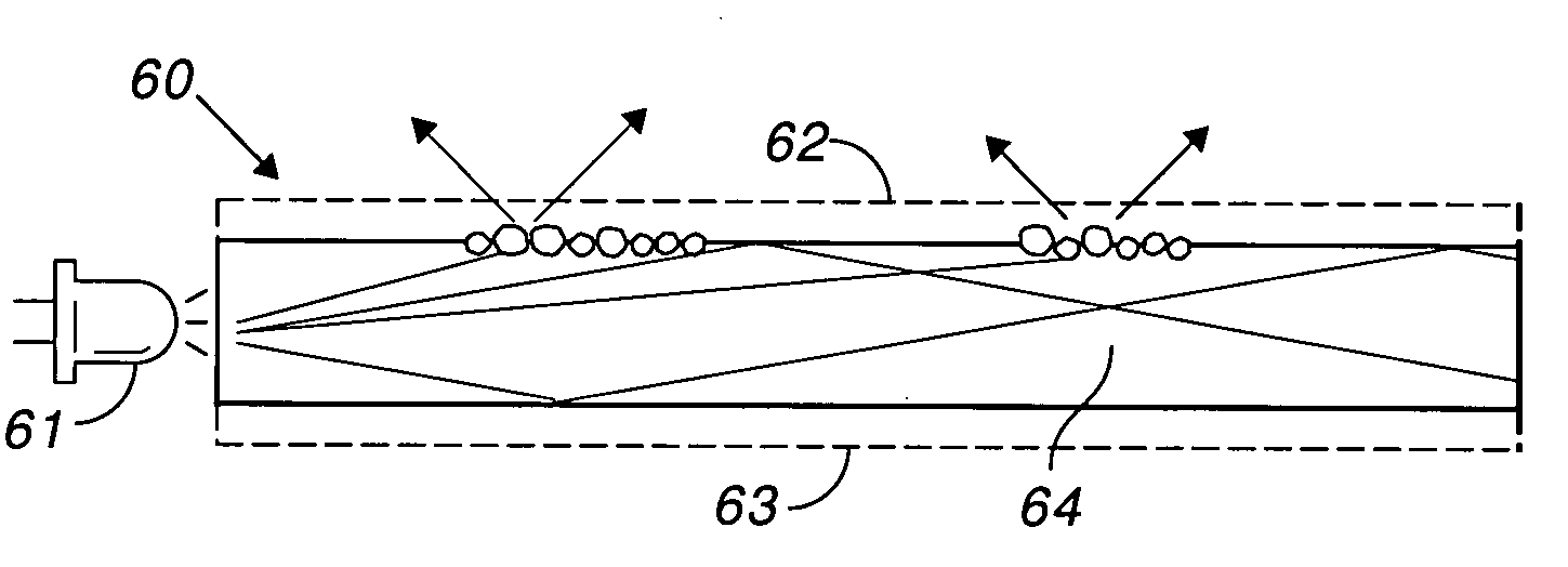
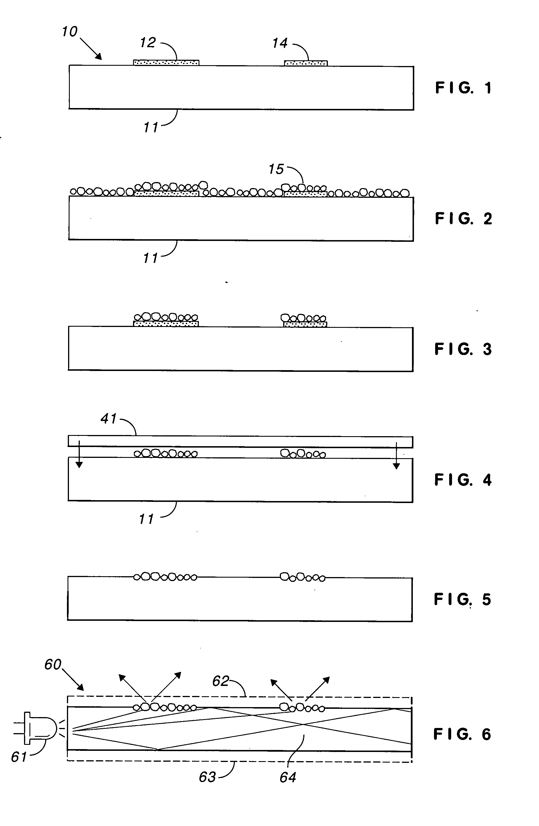
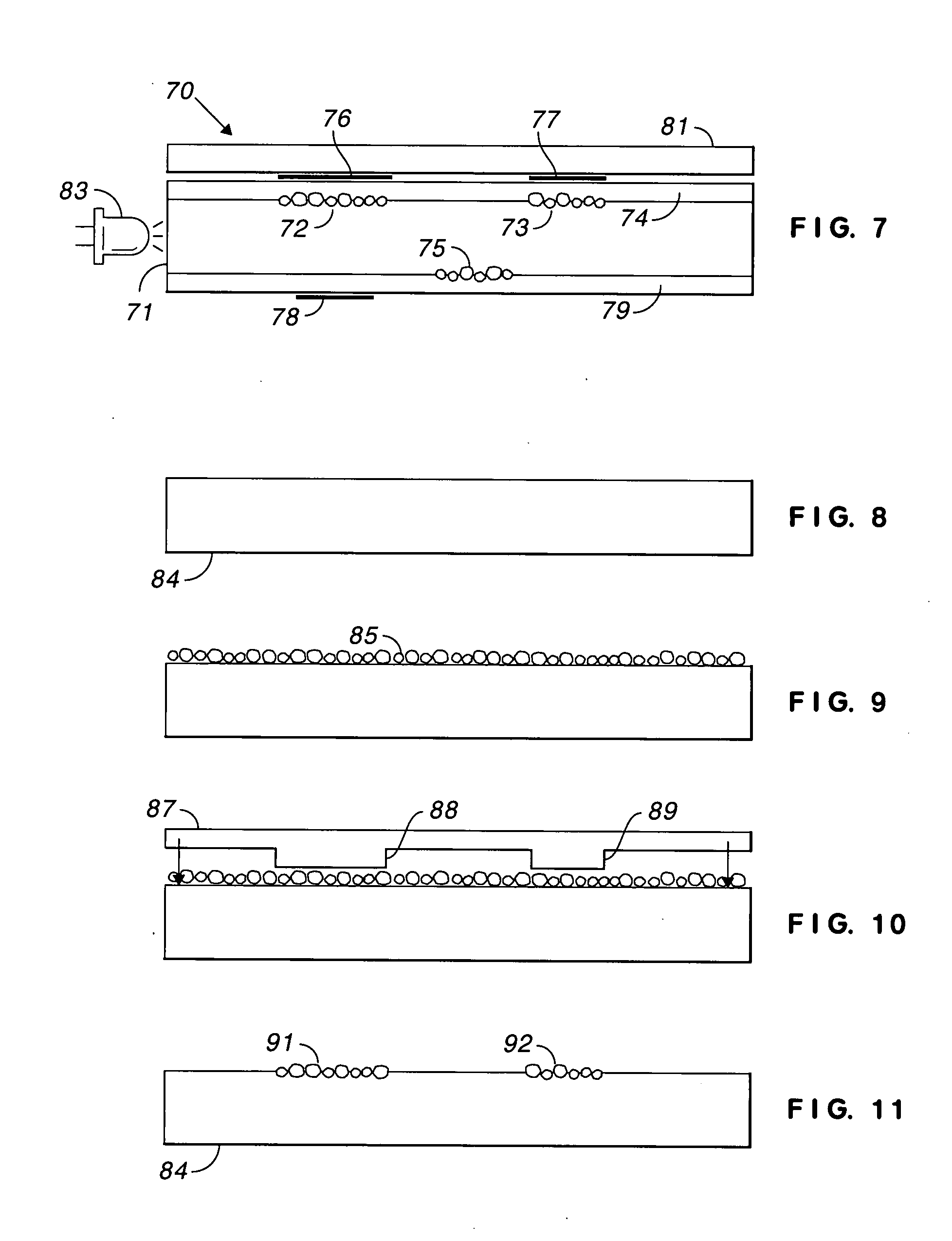
[0024]In FIG. 1, light guide 10 includes transparent sheet 11, such as glass or polymer, such as polyvinylidene fluoride (PVDF), polyester, or vinyl; preferably polycarbonate. The thickness of the transparent sheet depends upon application. Light guides have been constructed in accordance with the invention using sheets having thicknesses of 5, 7, and 10 mils (0.13 mm, 0.18 mm, and 0.25 mm). Other thicknesses can be used. The required characteristic is not polycarbonate or thickness but total internal reflection in at least one direction. The term “sheet” is used for convenience. The light guide can be a rod, a cone, a cylinder, or other shape. Any reference to geometrical shape is understood in a physical sense, not in a mathematical sense wherein, for example, a cylinder is a surface, having no thickness.

[0025]As known in the art, total internal reflection requires that the index of refraction of the light guide be higher than the index of refraction of the surrounding material. I...


PUM

PropertyMeasurementUnit
Adhesivityaaaaaaaaaa
Areaaaaaaaaaaa
Transparencyaaaaaaaaaa

Abstract

A light guide includes a transparent sheet exhibiting total internal reflection in at least one direction and phosphor printed on the transparent sheet. The phosphor extracts light from the transparent sheet when the sheet is edge-lit and converts the light from one wavelength to another wavelength. The phosphor is pressed into the surface of the sheet after heating the surface to its softening temperature.

Description

FIELD OF THE INVENTION[0001]This invention relates to back lights for keypad, keyboards, displays, and other electronic devices (collectively referred to herein as “displays”) and, in particular, to a light guide having phosphor imprinted into at least one major surface of the light guide.BACKGROUND OF THE INVENTION[0002]Edge lit sheets have long been known in the art; e.g. U.S. Pat. No. 3,027,669 (Hardesty) and U.S. Pat. No. 3,356,839 (Mehess et al.). Edge lit keypads are also known in the art. For example, U.S. Pat. No. 3,892,959 (Pulles) discloses peripheral cavities for receiving light emitting diodes (LEDs); U.S. Pat. No. 4,177,501 (Karlin) discloses peripheral cavities for receiving light sources; U.S. Pat. No. 4,247,747 (Swatten) discloses LEDs optically coupled to a polyester sheet having a thickness of seven mils (0.18 mm); and U.S. Pat. No. 5,975,711 (Parker et al.) discloses a light conductive panel coupled to a light source.[0003]It has long been known in the art to add ...

Claims


Application Information

Patent Timeline
IPC IPC(8): F21V8/00C03B37/023F21V7/04F21V9/16H01L33/00H01L33/50H01L33/60
CPCG02B6/0065G02B6/0043G02B6/00
Inventor SANCHEZ, OSCAR OZUNA
Owner WORLD PROPERTIES
Why Eureka
Try Eureka