Plastic optical fiber cable

a technology of optical fiber and plastic fiber, applied in the direction of optical fiber with multi-layer core/cladding, optical waveguide light guide, instruments, etc., can solve the problems of increasing transmission loss, increasing transmission loss, and high cost of quarter-inch optical fibers, and achieves the effect of long-term heat resistan

Active Publication Date: 2009-03-12
MITSUBISHI CHEM CORP
View PDF3 Cites 11 Cited by
  • Summary
  • Abstract
  • Description
  • Claims
  • Application Information

AI Technical Summary

Benefits of technology

0027]The present invention can provide a plastic optical fiber cable that significantly excels in long-term heat resistance in a high-temperature environment.

Problems solved by technology

The quartz optical fibers, however, are expensive and poor in workability.
In the configuration in which the POF is in close contact with the coating layer made of a polyamide resin, like the POF cable described in Patent Documents 1 to 3, these monomers and oligomers dissolve and diffuse into the POF in a high-temperature environment, resulting in increase in transmission loss.
In particular, when the outermost layer of the clad is made of a fluorine-containing olefin resin and contains a tetrafluoroethylene (TFE) unit as well as at least one of a vinylidene fluoride (VdF) unit and a hexafluoropropylene (HFP) unit, the transmission loss significantly increases.
However, when the monomers and oligomers described above are cyclic lactam compounds, the monomers and oligomers move to the vicinity of the interface to the inner layer side of the clad layer (the core or the first clad layer) to form particulate structures, resulting in increase in structure mismatching at the interface to the POF and hence significant degradation in transmission characteristics of the POF cable.
When used in an automobile, a POF cable is required to show small increase in transmission loss for a long period, longer than 5000 hours, in an environment at 105° C. However, the POF cables described in Patent Documents 1 to 3, when the POFs are directly coated with polyamide resin, show increase in transmission loss in a high-temperature environment from the reasons described above, so that the POF cables are not good enough to satisfy the requirements.

Method used


Image

  • Plastic optical fiber cable
  • Plastic optical fiber cable
  • Plastic optical fiber cable

Examples


example 1

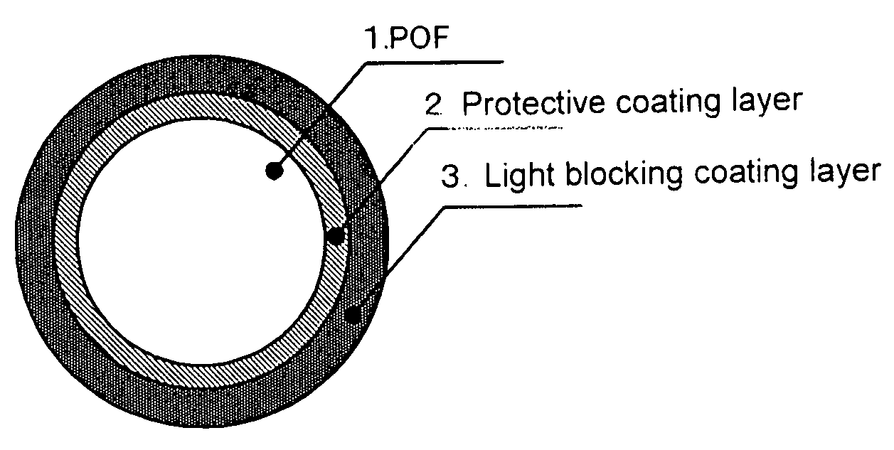
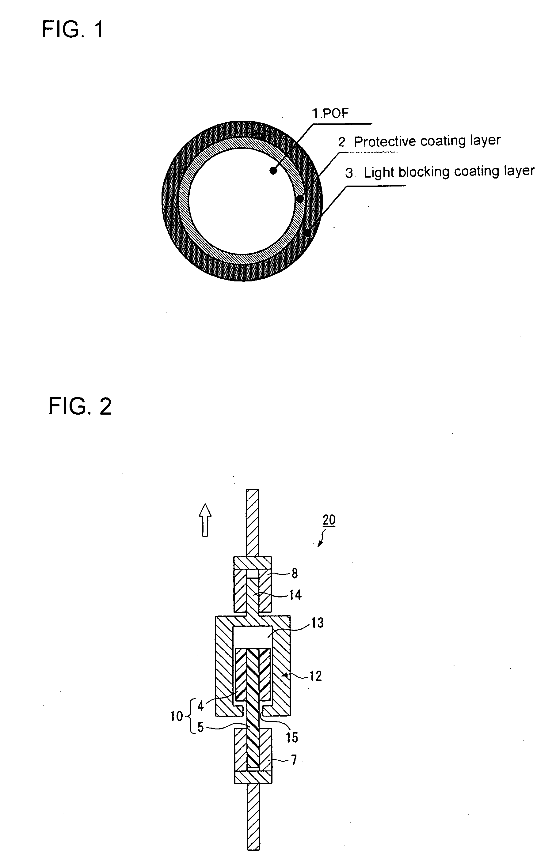
[0126]The cable coating apparatus equipped with a crosshead die set at 210° C. was used to fabricate a POF in a way similar to Comparative Example 1 described above. The outer surface of the POF was coated with a MMA / MAA copolymer (composition ratio: 98 / 2 (% by weight), melt flow index: 60 g / min) as the protective coating material, and the outer surface of the protective coating was coated with a commercially available nylon 12 resin (Daicel-Degussa Ltd., Model Name: Daiamide-L1640) having a terminal amino group content of 2 μeq / g or lower, to which 1% by weight of carbon black was added. The above coating process was performed through co-extrusion. There was thus provided a POF cable having the protective coating layer (thickness: 60 μm) and the light blocking coating layer (thickness: 190 μm), the outer diameter of the POF cable being 1.5 mm. Various evaluations were conducted on the resultant POF cable, and the evaluation results are shown in Table 2.

example 2

[0127]The same materials as those used in Example 1 were used for the core material, the first clad material, the second clad material, and the protective coating layer. These polymers were melted, supplied to the spinning fiber head at 230° C., and underwent a conjugate fiber spinning process by using the concentric conjugate nozzles. Then, in the hot air furnace at 140° C., the resultant fiber was drawn to be twice in length in the fiber axis direction. A 1 mm-diameter POF in which the thickness of each of the first clad, the second clad, and the protective coating layer was 10 μm was thus provided. The resultant POF had a good initial transmission loss of 134 dB / km. The outer surface of the POF was coated with the same light blocking coating layer as that in Example 1 through co-extrusion. A POF cable having an outer diameter of 1.5 mm was thus fabricated. Various evaluations were conducted on the resultant POF cable, and the evaluation results are shown in Table 2.

example 3

[0128]PMMA (refractive index: 1.492) was used for the core material. A copolymer of VdF / TFE / HFP / PFPVE (composition ratio: 21 / 55 / 18 / 6 (% by weight), refractive index: 1.350, crystal melting heat (ΔH): 8 mJ / mg) was used for the clad material. A MMA / MAA / butylacrylate (BA) copolymer (composition ratio: 88 / 2 / 10 (% by weight), melt flow index: 61 g / min) was used for the protective coating layer. A method similar to that used in Example 2 was used to provide a POF having a diameter of 1 mm in which the thickness of each of the clad and the protective coating layer was 10 μm. The resultant POF had a good initial transmission loss of 132 dB / km. The outer surface of the POF was coated with a commercially available nylon 11 resin (Atofina, Model Name: RILSAN BMF-0) as the light blocking coating layer, to which 1% by weight of carbon black was added, in a way similar to Example 2. A POF cable was thus fabricated. Various evaluations were conducted on the resultant POF cable, and the evaluation ...


PUM

PropertyMeasurementUnit
temperatureaaaaaaaaaa
heat resistanceaaaaaaaaaa
temperatureaaaaaaaaaa

Abstract

The invention provides a plastic optical fiber cable comprising a plastic optical fiber having a core/clad structure, a light blocking coating layer provided around the plastic optical fiber, and a protective coating layer provided between the outermost layer of the core/clad structure and the light blocking coating layer. The outermost layer of the core/clad structure is made of a fluorine-containing olefin polymer containing at least a tetrafluoroethylene unit, the crystal melting heat of the fluorine-containing olefin polymer being 59 mJ/mg or lower. The light blocking coating layer is made of a resin primarily containing a polyamide resin, the content of polyamide resin-derived monomers and oligomers being 1.5% by weight or lower.

Description

TECHNICAL FIELD[0001]The present invention relates to a plastic optical fiber cable, and particularly to a plastic optical fiber cable with excellent long-term heat resistance in a high-temperature environment approximately at 100 to 125° C.BACKGROUND ART[0002]Conventional optical fibers made of quartz, having a capability of excellent optical transmission across a broad wavelength spectrum, have been in practical use mainly for trunk lines. The quartz optical fibers, however, are expensive and poor in workability. Therefore, plastic optical fibers (hereinafter abbreviated as POF), which are less inexpensive, have lighter weight, larger apertures, and easily workable end surfaces, are easily handled, and have other advantages, have been in practical use in a lighting application, a sensor application, and an interior wiring application, such as FA, OA and LAN.[0003]Among various POFs, a step-index (SI) POF having a core / clad structure using polymethyl methacrylate (PMMA) as the core...

Claims


Application Information

Patent Timeline
Patent Type & Authority Applications(United States)
IPC IPC(8): G02B6/036
CPCG02B1/048G02B6/02033G02B6/00
Inventor AOYAGI, AMANETSUKAMOTO, YOSHIHIROFUJISHIGE, YASUSHI
Owner MITSUBISHI CHEM CORP
Why Eureka
Try Eureka