Microfluidic assay system with dispersion monitoring

a microfluidic assay and monitoring technology, applied in the field of microfluidic assay systems with dispersion monitoring, can solve the problems of difficult to achieve in microfluidic devices, limited etc., to improve the quality and reliability of data, reduce or correct sources of errors, and improve the accuracy of quantitative determinations using microfluidic devices

Inactive Publication Date: 2009-03-12
UNIV OF WASHINGTON
View PDF9 Cites 41 Cited by
  • Summary
  • Abstract
  • Description
  • Claims
  • Application Information

AI Technical Summary

Benefits of technology

[0011]The invention provides a microfluidic assay system and methods that incorporate principles of flow injection analysis. Since the concentration of solutes within microfluidic assay devices may be very sensitive to dispersion effects, the accuracy of quantitative determinations using microfluidic devices is limited. The methods permit dispersion monitoring to improve the quality and reliability of data by reducing or correcting sources of error. The contents of a fluidic stream can be compared to a baseline as it flows over a detector array. This permits monitoring of the flow rate, flow pattern, and solute distribution and concentration. Th...

Problems solved by technology

Since the concentration of solutes within microfluidic assay devices may be very sensitive to dispersion effects, the accuracy of quantitative determinations using microfluidic ...

Method used


Image

  • Microfluidic assay system with dispersion monitoring
  • Microfluidic assay system with dispersion monitoring
  • Microfluidic assay system with dispersion monitoring

Examples


example 1

Biosensor Operation

[0079]SPR imaging apparatus and the microfluidic devices have traditionally been used to conduct small-molecule immunoassays. Note that while this describes a specific assay format, other formats are compatible with the techniques disclosed herein, such as direct detection (capture molecule on surface, binding event between capture molecule and analyte detected directly), sandwich immunoassay formats, etc. However, since our research is focused on using SPR imaging as the detection methodology, and since our targets of interest are small molecules, and because SPR does not typically have adequate sensitivity to directly detect binding of small molecules, an indirect detection method has been used instead. This has been accomplished by mixing an antibody to the analyte of interest into a buffer solution containing the analyte, then flowing the mixture through the microfluidic device and over the sensor functionalized with an analogue of the analyte. Antibody molecu...

example 2

Pulsed Sample Injection

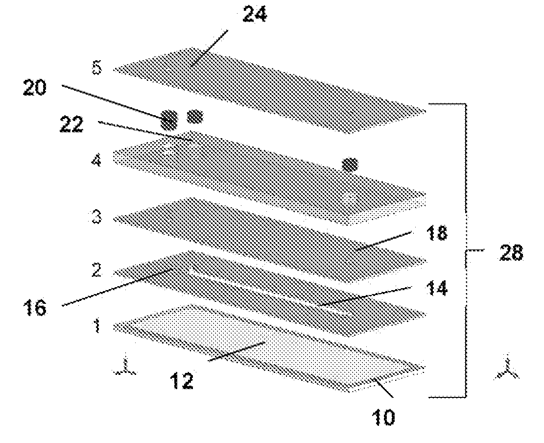
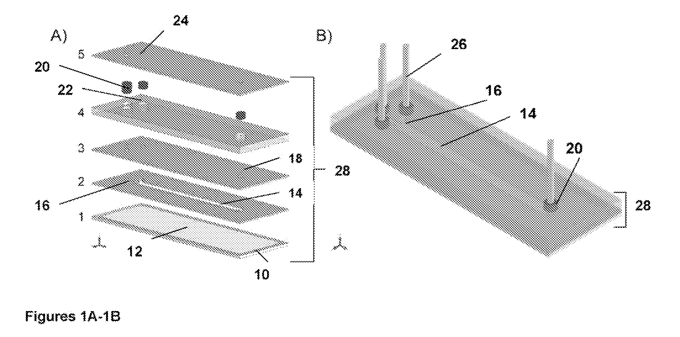
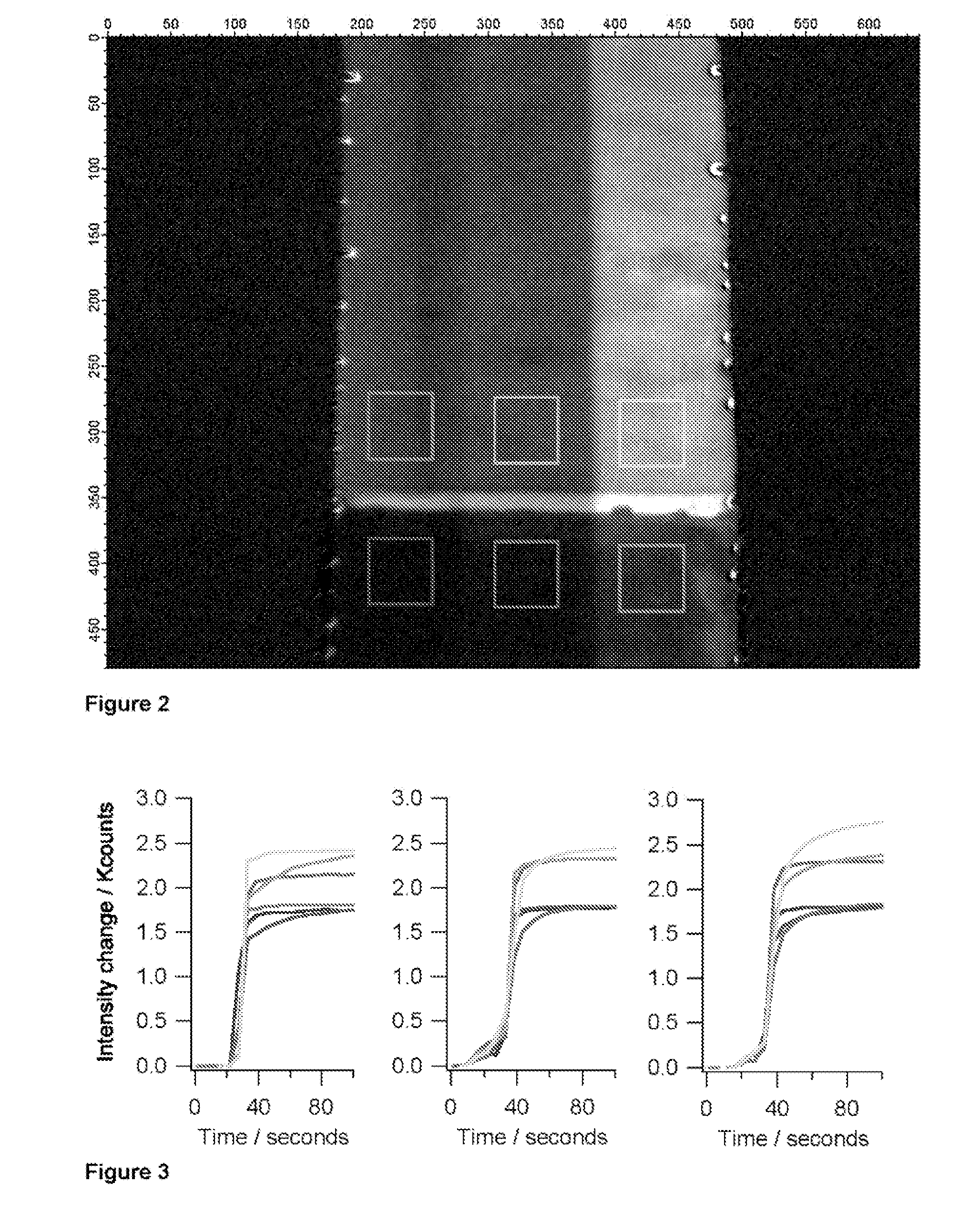
[0085]A simple microfluidic device layout that enables the generation of a bolus or pulse of a sample and the delivery of that pulse into a channel that is previously filled with a carrier solution involves injection of sample at the upstream end. By adding a small amount of salt (or some other substance that changes the refractive index of the sample relative to the carrier fluid) via an orthogonal injection channel, SPR provides the ability to readily monitor the location and distribution of the pulse as it traverses the imaging area. By dividing the detector area into non-binding and binding areas, and by including a molecule in the sample that will specifically adsorb to the binding area, it is possible to monitor the accumulation of the adsorbate and correlate that to the distribution and other properties of each sample pulse.

[0086]The lower (upstream) two-thirds of the channel surface have been treated with a PEG-terminated thiol, while the upper third o...

example 3

Assay Calibration for Quantitative Analysis

[0087]Device calibration is essential for a point-of-care diagnostic instrument to provide valid quantitative data. Precise and accurate knowledge of fluid volumes delivered across the sensor surface, solute concentrations, flow rates, solute distribution within and across the channel and dispersion factors is required for quantitating an assay. Solutions with added standards and controls for surface fouling and other effects may also be needed. This latter point is one of the important rationales for having separate fluid inlets into a common channel, that is, to provide for run-time controls and calibrants necessary for quantitative determination. Implementing such controls imposes a strict condition on the ability to make valid comparisons among the sensor responses in each separate stream.


PUM


Abstract

Disclosed is a microfluidic assay system and methods that apply flow injection analysis to permit dispersion monitoring. A solution containing a reagent that binds an analyte and a tracer is delivered via pressure-driven flow into the receiving end of the injection channel of the system of the invention. A sample fluid suspected of containing the analyte is delivered into the upstream end of the input channel under conditions permitting flow of the sample fluid toward the downstream end of the assay channel and permitting dispersion of the reagent into the sample fluid. The amount of tracer present in the fluid as it passes over the reference region and the capture region and the amount of binding between the analyte and the capture region are detected. The amount of binding detected between the analyte and the capture region is correlated to the amount of tracer detected in the reference region.

Description

[0001]This application claims the benefit of U.S. provisional patent application No. 60 / 971,463, filed Sep. 11, 2007, the entire contents of which are incorporated herein by reference,TECHNICAL FIELD OF THE INVENTION[0002]This invention relates generally to methods and devices using dispersion monitoring to improve the quality and reliability of quantitative assays performed in a microfluidic environment. The invention allows the benefits of dispersion within fluidic samples that create mixing of analytes and reagents while reducing or correcting sources of error that result from dispersion.BACKGROUND OF THE INVENTION[0003]Developments in microfluidic technology and micro-total analytical systems (microTAS) have proceeded rapidly over the past two decades (Auroux, et al. 2002, Analytical Chemistry 74(12): 2637-2652; Reyes, et al. 2002, Analytical Chemistry 74(12); 2623-2636; Dittrich, et al. 2006, Analytical Chemistry 78(12); 3887-3908). Microfluidic technology promises to have majo...

Claims


Application Information

Patent Timeline
IPC IPC(8): G01N33/543B01J19/00G01N33/536
CPCG01N33/558B01L3/502746
Inventor NELSON, KJELL E.YAGER, PAUL
Owner UNIV OF WASHINGTON
Why Eureka
Try Eureka