Ultrasonic diagnostic apparatus, ultrasonic image processing apparatus and ultrasonic image processing method

Active Publication Date: 2009-03-12
TOSHIBA MEDICAL SYST CORP
View PDF0 Cites 25 Cited by
  • Summary
  • Abstract
  • Description
  • Claims
  • Application Information

AI Technical Summary

Benefits of technology

[0006]The invention is contrived in view of the above-mentioned situation. An object of the invention is to provide an ultrasonic diagnosis device, an ultrasonic image proces

Problems solved by technology

However, in the past display of strain gauge, only the movement state of a segment between two points connecting an inner membrane position and an outer membrane position is expressed and thus the motion information of the cardiac ti

Method used


Image

  • Ultrasonic diagnostic apparatus, ultrasonic image processing apparatus and ultrasonic image processing method
  • Ultrasonic diagnostic apparatus, ultrasonic image processing apparatus and ultrasonic image processing method
  • Ultrasonic diagnostic apparatus, ultrasonic image processing apparatus and ultrasonic image processing method

Examples


Example

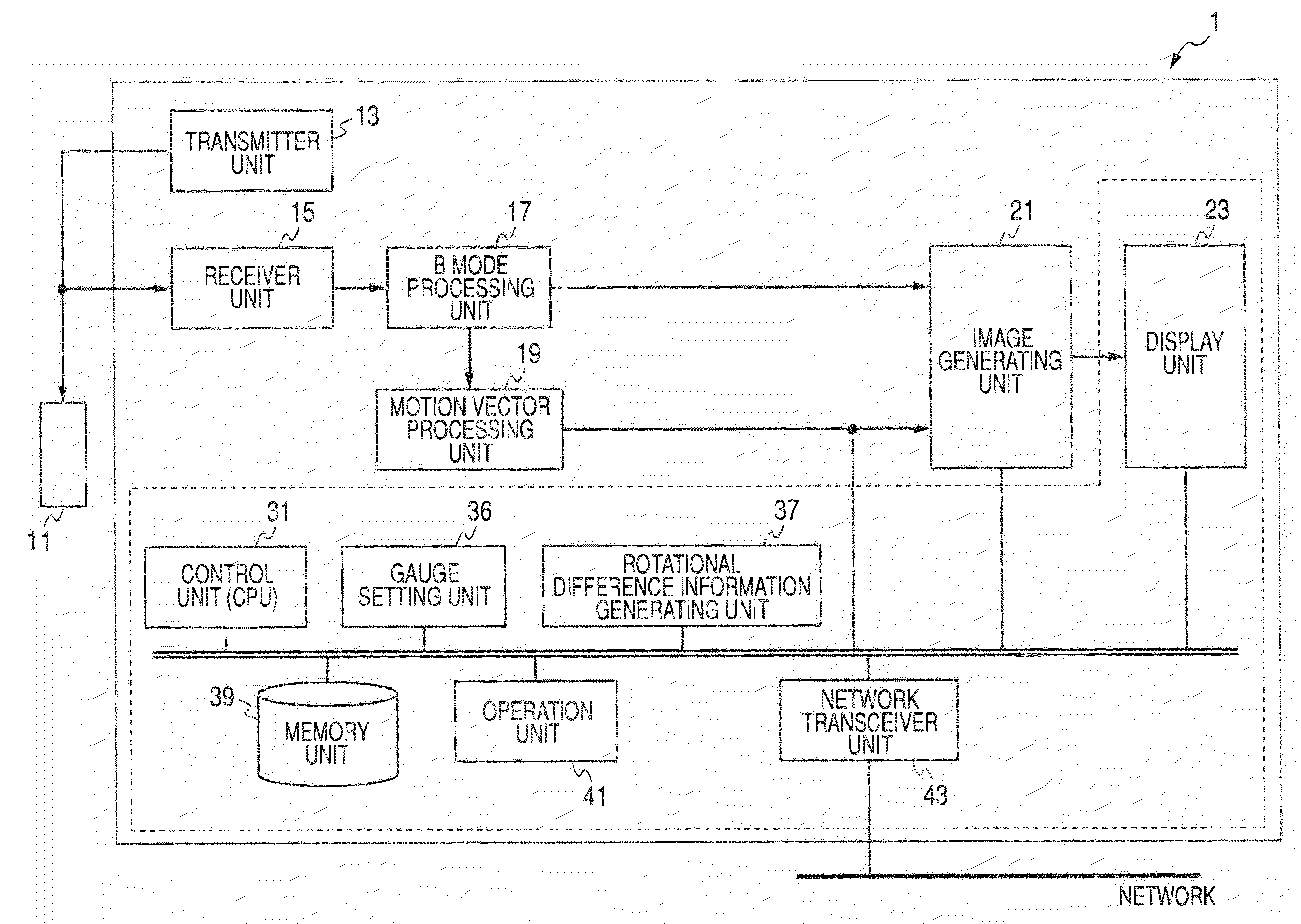
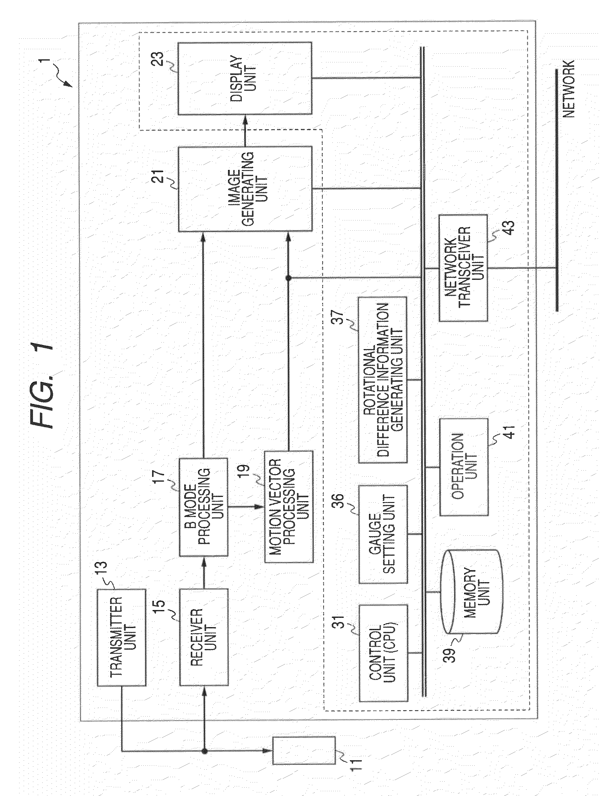
[0018]Hereinafter, embodiments of the invention will be described with reference to the accompanying drawings. In the following description, elements having substantially like functions and configurations will be denoted by like reference numerals or signs and the repeated description thereof is made only if necessary.

[0019]In this embodiment, the technical idea of the invention is applied to an ultrasonic diagnosis device. However, the invention is not limited to the ultrasonic diagnosis device, but the technical idea of the invention can be applied to an ultrasonic image processing device using a work station or a personal computer.

[0020]Functions embodied by the elements of this embodiment, particularly, functions embodied by a motion vector processing unit 19, a gauge setting unit 36, and a rotational difference information generating unit 37 (see FIG. 1) to be described later, can be also embodied by installing software programs for performing the same processes as the above-me...


PUM


Abstract

Plural strain gauges which are folded lines defined by gauge end points and gauge middle points are set up every time phase using motion vector information of a tissue and a strain gauge image in which the strain gauges are overlapped at a corresponding position of an ultrasonic image at each time phase is generated and displayed. A rotation angle from a reference time phase is calculated, rotational difference information between the gauge end points is generated and displayed in a predetermined form for the respective gauge end points (and the gauge middle points if necessary). Accordingly, for example, by setting the gauge end points in an inner membrane and an outer membrane of a cardiac muscle and setting the gauge middle points in an intermediate membrane, quantitative information is generated such as the rotational difference between the inner and outer membranes in local regions of the cardiac muscle or in the global cardiac muscle or the rotational difference of the inner membrane and the outer membrane relative to the intermediate membrane.

Description

CROSS-REFERENCE TO RELATED APPLICATIONS[0001]This application is based upon and claims the benefit of priority from prior Japanese Patent Application No. 2007-233277, filed Sep. 7, 2007, the entire contents of which are incorporated herein by reference.BACKGROUND OF THE INVENTION[0002]The present invention relates to an ultrasonic diagnosis device, an ultrasonic image processing device, and an ultrasonic image processing method for supporting intuitive grasp of a complex wall motion due to a multi-layered structure of a cardiac muscle, for example, by overlapping and displaying gauges divided between inner and outer membranes of a heart with an ultrasonic image when strain is observed using the ultrasonic image.[0003]It is very important in diagnosing a biological tissue such as a cardiac muscle to objectively and quantitatively estimate functions of the biological tissue. In recent years, a variety of quantitative estimation methods were tried mainly for the heart.[0004]For example...

Claims


Application Information

Patent Timeline
IPC IPC(8): A61B8/08
CPCA61B8/08A61B8/485A61B8/0883
Inventor ABE, YASUHIKO
Owner TOSHIBA MEDICAL SYST CORP
Why Eureka
Try Eureka