Remote control method for a motion heading by referring to a relative angle between a receiving end and a transmission end

a technology of a transmission end and a receiving end, which is applied in the direction of distance measurement, navigation instruments, instruments, etc., can solve the problems of frequent occurrence of awkward situations and car trampling

Active Publication Date: 2009-03-12
HONGBO WIRELESS COMM TECH CO LTD
View PDF8 Cites 9 Cited by
  • Summary
  • Abstract
  • Description
  • Claims
  • Application Information

AI Technical Summary

Benefits of technology

[0006]The primary purpose of the present invention is to provide a method to control a motion heading at a receiving end by referring to a relative angle between the receiving end and a transmission end to solve th...

Problems solved by technology

However, the moving control of all RC model cars generally available in the market is done by having the head of the car as a reference direction; therefore, a player is frequently caught in an awkward situation that the car moves in opposite direction to that as commanded by the joystick.
That is, with the head of the model car facing the player, the p...

Method used


Image

  • Remote control method for a motion heading by referring to a relative angle between a receiving end and a transmission end
  • Remote control method for a motion heading by referring to a relative angle between a receiving end and a transmission end
  • Remote control method for a motion heading by referring to a relative angle between a receiving end and a transmission end

Examples


Embodiment Construction

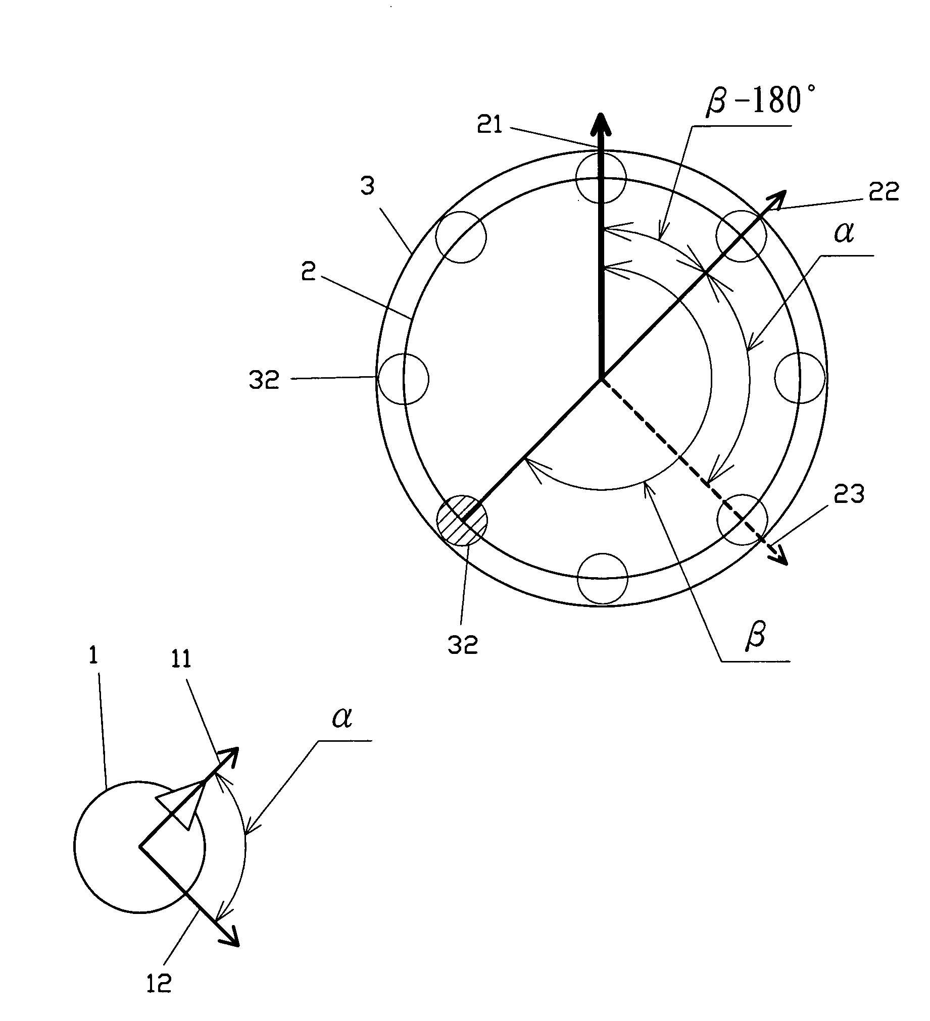
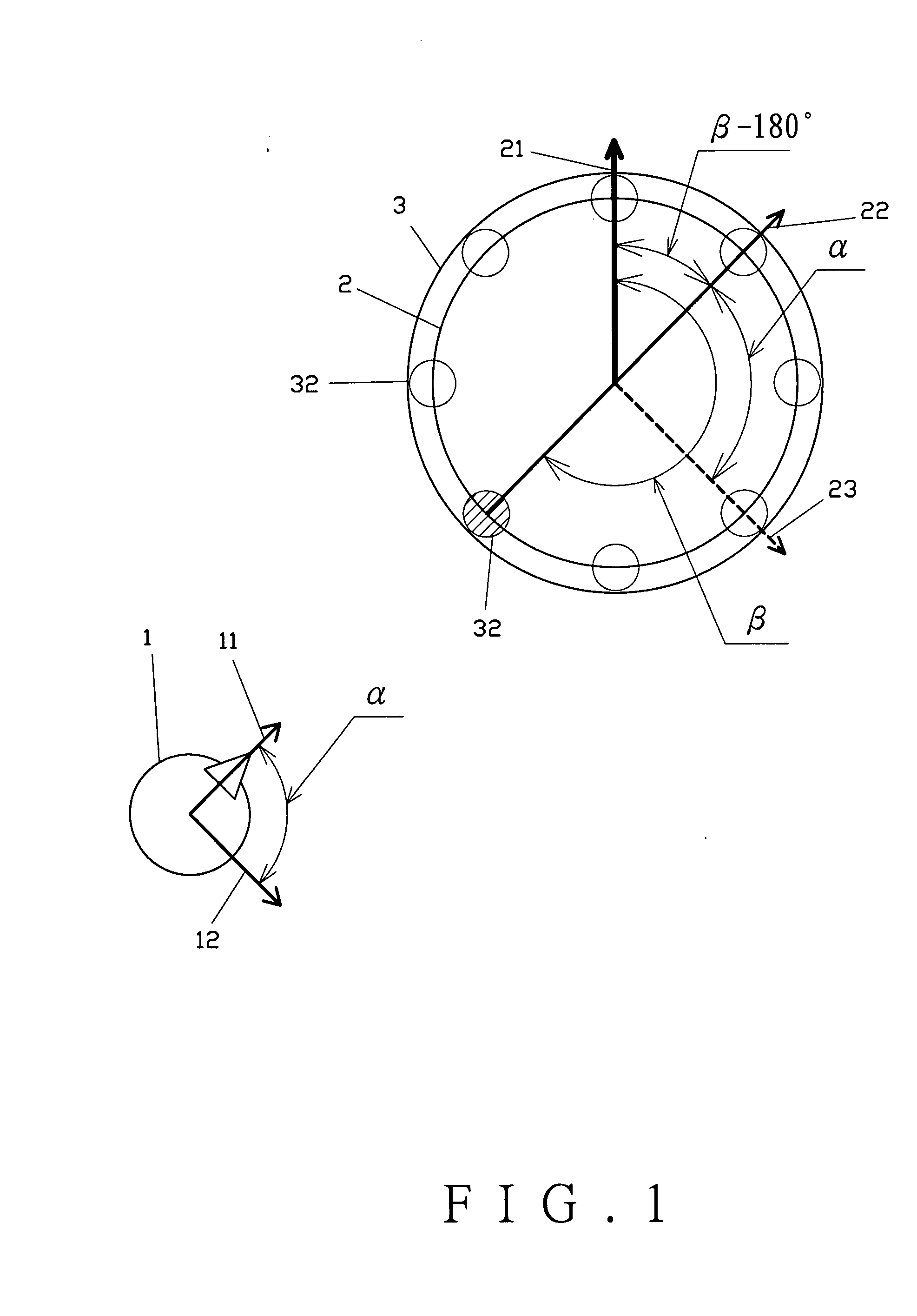
[0029]Referring to FIGS. 1, 2 and 3 for a first preferred embodiment of the present invention, a method to control a motion heading at a receiving end by referring to a relative angle between a receiving end and a transmission end comprises the following steps:

[0030]Step A: Obtaining an angle, α, which is between an original heading (11) of the transmission end (1) and a user inputted direction (12). The value of the obtained angle will be transmitted to the receiver as a command;

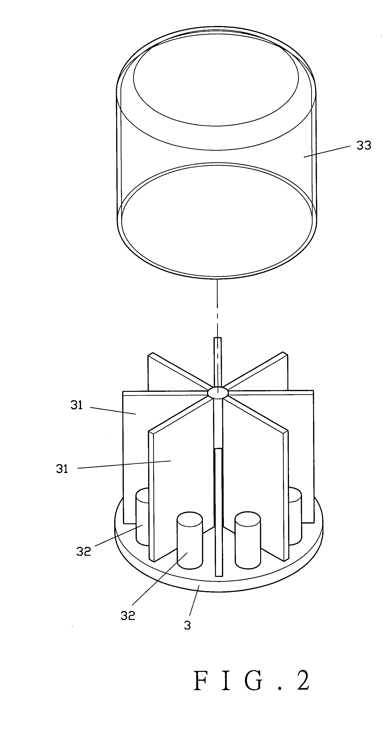
[0031]Step B: having a signal-receiving unit (3) at a receiving end (2) to pick up signals (13) (the command angle α) sent from the transmission end (1);

[0032]Step C: determining a signal source orientation (22) according to strength of the signals (13) received by the signal-receiving unit (3) which comprises multiple sensors (32) or a position sensitive device (not shown in the drawings) arranged in a form that is sufficient to pick up the signals (13);

[0033]Step D: solving a relative angle, β, between th...


PUM


Abstract

A method to control a motion heading at a receiving end by referring to a relative angle between the receiving end and a transmission end includes the following steps: Step A: solving a command angle, α, between an original heading and a user inputted direction of transmission end; Step B: having a signal-receiving unit at the receiving end to pick up signals sent from the transmission end; Step C: determining a signal source orientation according to strength of the signals received by the signal-receiving unit which comprises multiple sensors or a position sensitive device arranged in a form to pick up the signals from the transmission end; Step D: solving a relative angle, β, between the signal source orientation and an original motion heading of the receiving end; and Step E: solving a new motion heading according to the angles α and β.

Description

BACKGROUND OF THE INVENTION[0001](a) Field of the Invention[0002]The present invention relates to a method to remote control a motion heading by referring to a relative angle between a receiving end and a transmission end, and more particularly, to a method for performing an angular computation based on signals of the relative angle picked up by the receiving end to generate a new motion heading identical with that set up by the transmission end.[0003](b) Description of the Prior Art[0004]A remote control device to control motion heading of a target object (a power toy, robot vehicle, etc.) usually contains a transmission end and a receiving end. Taking an RC model car for example, a remote controller is the transmission end; and the model car, the receiving end. A joystick provided on the remote controller executes remote control over advancing, reversing, and taking turns of the model car. However, the moving control of all RC model cars generally available in the market is done b...

Claims


Application Information

Patent Timeline
IPC IPC(8): G05D3/00
CPCG08C17/02G08C2201/50G08C2201/32
Inventor SHEU, YIH-RAN
Owner HONGBO WIRELESS COMM TECH CO LTD
Why Eureka
Try Eureka