

Method of transmitting data
- Summary
- Abstract
- Description
- Claims
- Application Information
AI Technical Summary
Benefits of technology
Problems solved by technology
Method used
Image

Examples
first embodiment
[0084]FIG. 3 is a diagram illustrating a process of segmenting a data block in consideration of a CRC size according to an exemplary embodiment of the present invention.
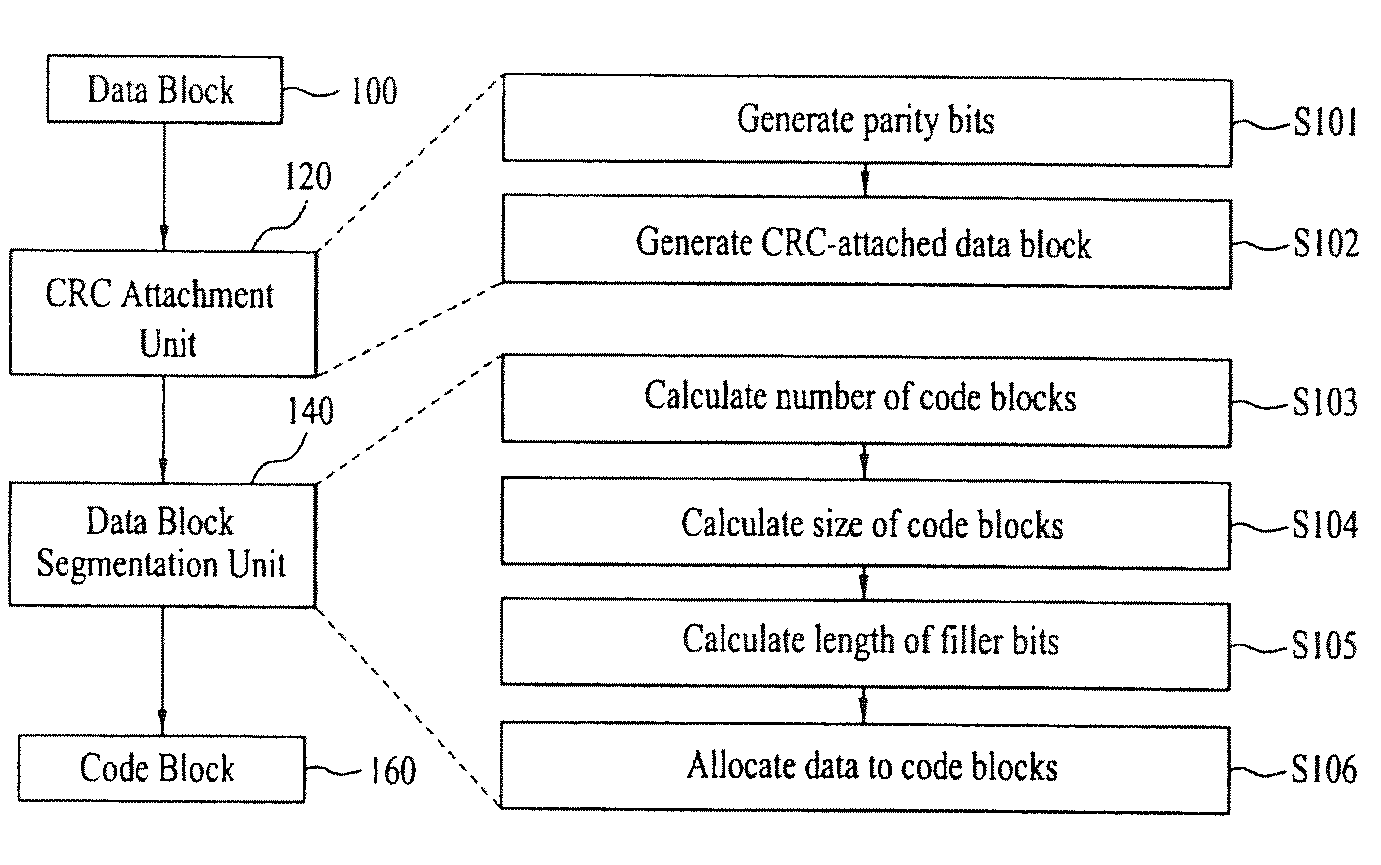
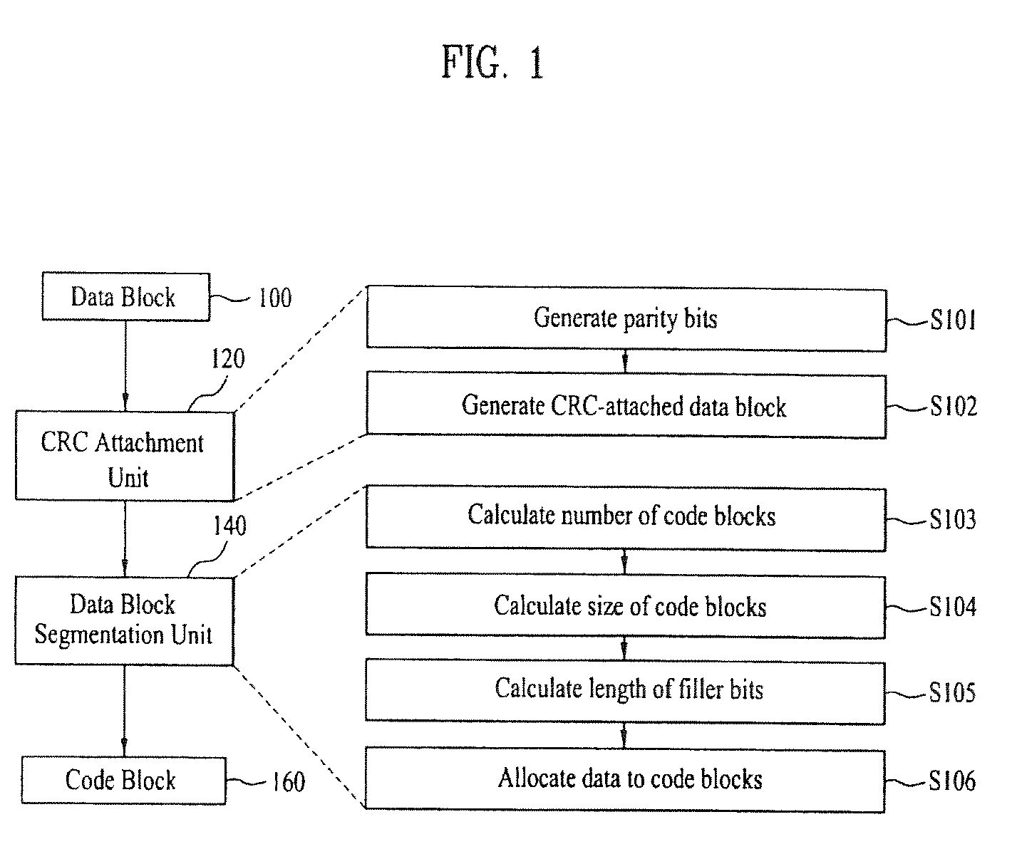
[0085]Referring to FIG. 3, a data block (for example, a first data block 300) is input to a data block segmentation unit 320 and segmented into one or more code blocks (for example, a second data block). Data is sequentially allocated to the code blocks. The code blocks are input to a CRC attachment unit 340. In this case, the data block may include an error detection code therein and the size of the error detection code is desirably 24 bits.
[0086]The CRC attachment unit 340 generates CRC codes and attaches the CRC codes to the code blocks, except when the data block is comprised of one code block including an error detection code (for example, except when a data block size B is less than or equal to a maximum code block size Z). Thus the data block 300 is segmented into the code block 360 through the data block segm...
second embodiment
[0173]FIG. 4 is a diagram illustrating an example of a process of attaching CRC codes to code blocks according to an exemplary embodiment of the present invention.
[0174]Referring to FIG. 4, a data block (a first data block 400) is input to a data block segmentation unit 420 and is segmented into code blocks (a second data block). Code blocks 430 in consideration of a CRC size are input to the CRC attachment unit 440 to generate a CRC-attached code block 460. This process is similar to the method of FIG. 3, except for steps 304 and S306 in FIG. 3.
[0175]Another exemplary embodiment of the present invention assumes that the size of the code block 430 input to the CRC attachment unit is equal to the size of the CRC-attached code block 460. That is, a CRC size is included in the size of the code block input to the CRC attachment unit. Accordingly, when calculating the number and size of code blocks with respect to input data, it is desirable for the data block segmentation unit to consid...
third embodiment
[0190]FIG. 5 is a diagram illustrating another example of a process of attaching CRC codes to code blocks according to an exemplary embodiment of the present invention.
[0191]In FIG. 5, the size of an input code block 530 input to a CRC attachment unit 540 has a value obtained by subtracting a CRC size L from the size of an output code block 560. Although the operation of a data block segmentation unit 520 for dividing a data block (a first data block 500) is similar to the operation of the data block segmentation units shown in FIG. 3 and FIG. 4, a method of allocating data to a code block (a second data block) and a method of generating a CRC-attached block are different from the methods shown in FIG. 3 and FIG. 4.
[0192]Namely, although a CRC size is considered to divide the data block, a CRC area is not ensured in the size of the code blocks input to the CRC attachment unit, which is different from the method shown in FIG. 4.
[0193]Referring to FIG. 5, the first data block 500 is i...
PUM
 Abstract
Description
Claims
Application Information