Electronic pipettor assembly

a technology of electronic pipettor and electronic pipettor, which is applied in the direction of analytical using chemical indicators, laboratory glassware, instruments, etc., can solve the problems of difficult to take advantage of many of the advances of hand-held pipettor, difficulty in achieving accuracy when pipetting such small aliquots, and inability to achieve difficulties, etc., to achieve the effect of improving pipetting accuracy

Active Publication Date: 2009-03-19
INTEGRA BIOSCI CORP
View PDF3 Cites 51 Cited by
  • Summary
  • Abstract
  • Description
  • Claims
  • Application Information

AI Technical Summary

Benefits of technology

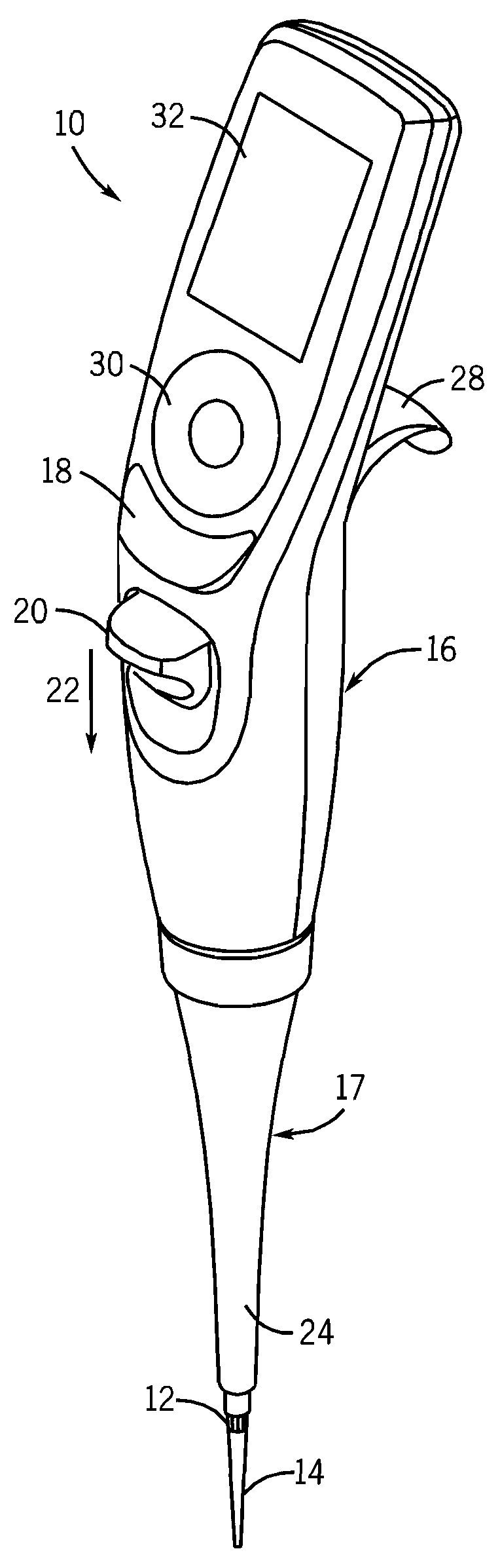
[0005]In one aspect, the invention is a hand-held electronic pipettor that is designed particularly to be programmed and operated with one hand for the convenience of the user. More specifically, the pipettor has an elongated body adapted to be held in hand of the user with a finger hook on the rear side of the body. On the front side of the body there is a touch wheel control that is operated by the thumb of the user or with a finger from the hand not holding the pipettor. A user interface display is also located on the front side of the pipettor and is located preferably above the touch wheel control. The pipettor preferably comprises a microprocessor which is programmed with menu driven software for controlling information displayed on the user interface display and for programming the microprocessor to operate the pipettor. The user programs the pipettor using the touch wheel control. A run button is located on the front side of the pipettor body as well, and is located below the touch wheel control. The run button likewise is designed to be operated by the thumb of the user. The user activates the run button in order to run a procedure or the next step in the procedure that is programmed into the pipettor. The front side of the pipettor also preferably includes an ejector button to be operated by the thumb of the user. The ejector button is used to activate the ejection mechanism to remove pipette tips mounted to the tip mounting shaft on the pipettor. The ejector button is preferably located below the run button. In this manner, the touch wheel control, run button and ejector button can all be conveniently operated by the thumb of the user.
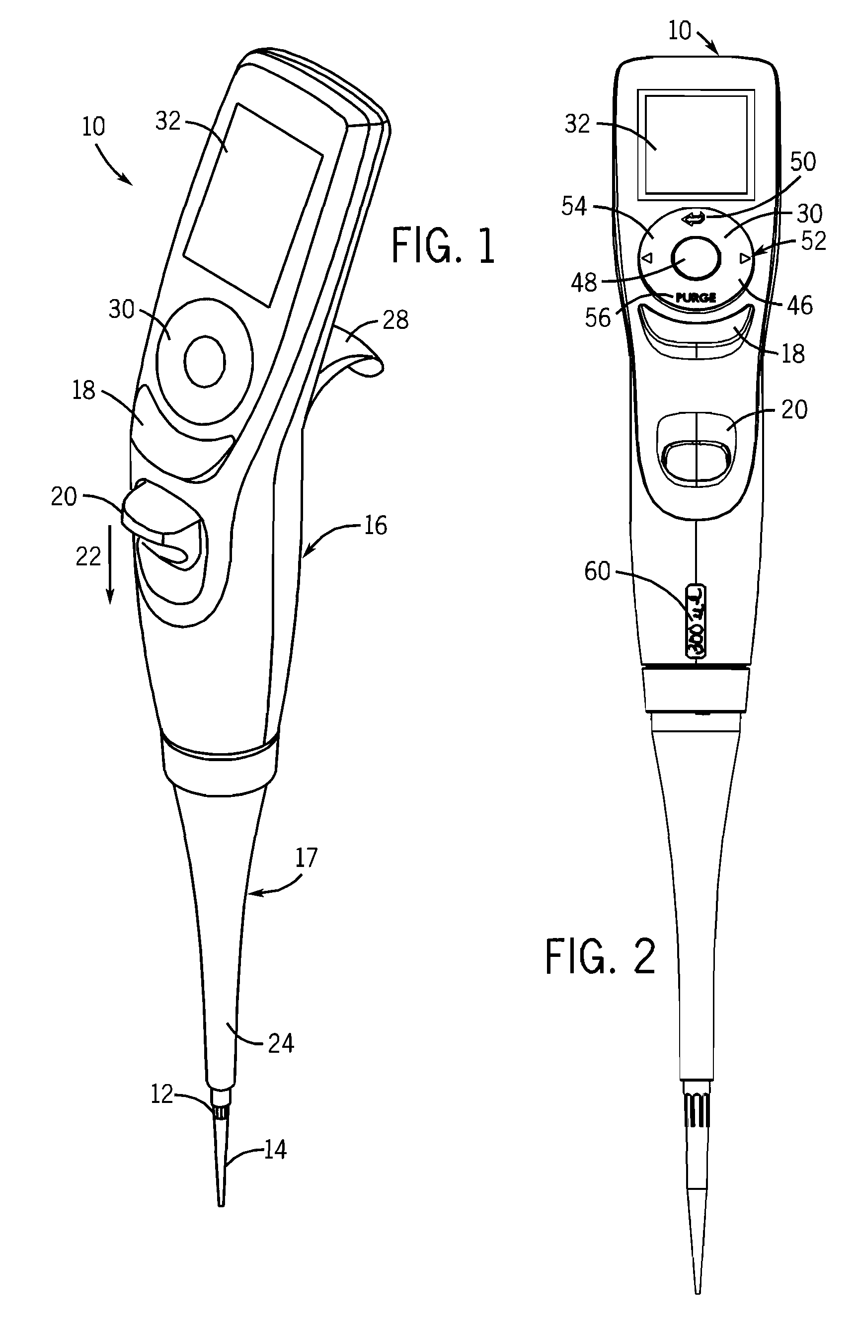
[0006]The preferred touch wheel control includes a circular touch pad that uses capacitance electronics to translate rotational movements of the thumb (or finger) into up and down cursor movements on the display, and an enter button located at the center of the circular touch pad. The circular touch pad also preferably includes four selector locations, namely a back button located at the top of the circular touch pad, right and left navigation buttons located on the right and left side of the circular touch pad, respectively, and a purge button located at the bottom of the circular touch pad. The back button allows the user to conveniently return to the previous screen or menu selection. The right and left navigation buttons allow the user to navigate via right or left menu prompts. The purge button allows the user to voluntarily stop the procedure and purge the pipettor, i.e., a full dispense and blow out, in order to purge the system to start another procedure. In accordance with the invention, each of these controls can be implemented conveniently using the thumb or finger of the user.
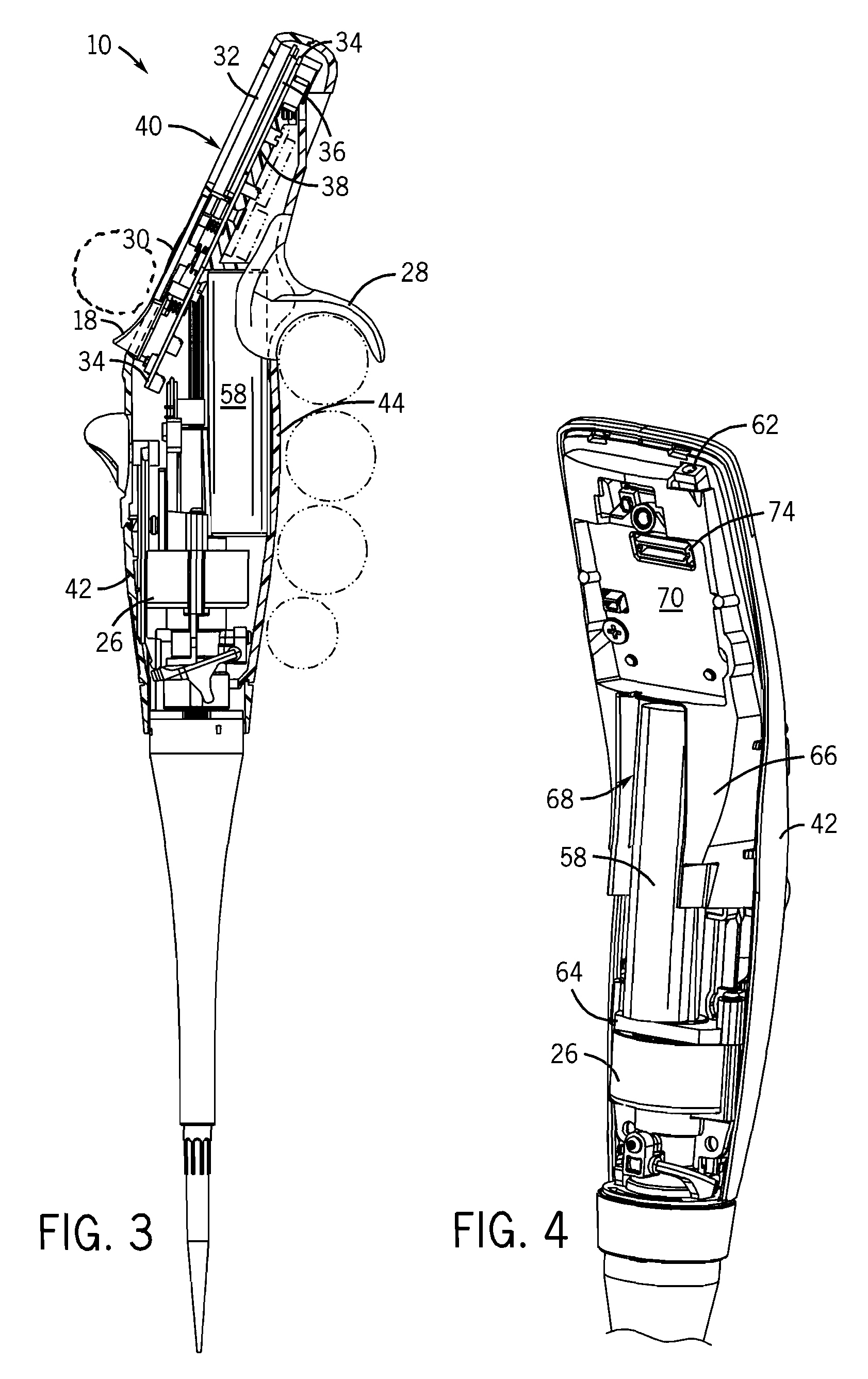
[0007]In accordance with another aspect of the invention, the pipettor is designed so that the center of gravity of the pipettor is located within the palm of the hand of the user holding the pipettor with their index finger wrapped around the housing underneath the finger hook located on the rear housing. This provides the user with a comfortable feel, and promotes accuracy in the placement of the physical location of the pipette tip by the user. In order to accommodate the relatively large number of electrical components on the pipettor, it is desirable to use a battery that has relatively significant weight, size and electrical storage capacity. Thus, it is preferred to use a battery having an elongated cylindrical shape as is common, but not typically used in connection with electronic pipettors. The housing is designed to provide structural support for the internal components of the pipettor, including the motor, and the elongated rechargeable battery. In accordance with this aspect of the invention, it has been found that mounting the battery in the housing so that the top of the battery is above the height of the finger hook, and the motor is mounted at a height substantially below the battery will locate the center of gravity of the pipettor in the palm of the hand of the user, and will also otherwise allow for the appropriate placement of internal pipettor components within the pipettor housing in a compact manner. In addition, the pipettor housing is designed with an internal vertical structure or wall which provides a compartment for the rechargeable battery, as well as preferably another compartment for an optional wireless communication chip. These compartments are accessible to the user if the user removes the rear housing, but the vertical structure isolates other electrical components from the user thereby protecting those other components, such as the color screen display, the capacitance circular touch pad, and a circuit board operating the pipettor.
[0010]In accordance with another aspect of the invention, when a user desires to dispense multiple aliquots, the pipettor uses a separate dispensing look-up table to determine the appropriate number of motor steps necessary to dispense the selected (or calculated) aliquot volume. The motor step values in the dispensing look-up table are empirically determined to account for dispensing inaccuracies. It has been found that the number of steps corresponding to aspirating a certain value is typically somewhat different than the number of steps for dispensing the same value, and therefore using separately developed empirical tables for as dispensing and aspirating can lead to significant improvements in dispensing accuracy especially when dispensing multiple aliquots of small volumes.

Problems solved by technology

To date, however, it has been difficult to take advantage of many of these advancements in hand-held pipettors.
Pipetting accuracy is especially important when working with small volumes, such as 1 or 2 μL aliquots, however, accuracy can be difficult to attain when pipetting such small aliquots.
Difficulties arise not only because of mechanical imprecision of the pipettor components, but also because liquid surface tension issues.
Inherently, there are normally differences between forces acting on liquids being aspirated and forces acting on liquids being dispensed, and these differences can cause meaningful inaccuracies when pipetting small volumes.

Method used


Image

  • Electronic pipettor assembly
  • Electronic pipettor assembly
  • Electronic pipettor assembly

Examples


Embodiment Construction

[0020]FIGS. 1-6 show a single channel pipettor 10 constructed in accordance with a preferred embodiment of the invention. While the embodiment shown is a single channel pipettor 10, it should be understood that many aspects of the invention may apply to multi-channel pipettors as well. The single channel pipettor 10 shown in the drawings is a hand-held electronic pipettor which is programmable by the user to aspirate and dispense liquid samples or reagents. The hand-held pipettor 10 includes a mounting shaft 12 onto which a disposable pipettor tip 14 is mounted as is known in the art. Although not shown in the drawings, the pipettor 10 includes an aspiration cylinder and a piston that is driven by motor 26 (see FIGS. 3-6) as will be explained in more detail below. The pipettor 10 has an elongated body consisting of an upper portion 16 and a lower portion 17. The aspiration cylinder and piston resides in the lower portion 17. A finger hook 28 is located on the rear side of the upper ...


PUM

PropertyMeasurementUnit
volumesaaaaaaaaaa
volumesaaaaaaaaaa
sizeaaaaaaaaaa

Abstract

A hand-held electronic pipettor is designed particularly to be programmed and operated with one hand for the convenience of the user. It uses a capacitance touchpad control for programming, and a separate run button for the operating mode. Internal components are located so that the center of gravity of the pipettor is located within the palm of the user. Flash memory stores an empirically derived table that correlates aspiration volume to motor steps and a separate empirically derived table the correlates dispensing volumes to motor steps.

Description

FIELD OF THE INVENTION[0001]The invention relates to improvements in hand-held electronic pipettors.BACKGROUND OF THE INVENTION[0002]The use of hand-held electronic pipettors is widespread in clinical and research laboratory applications. Electronic pipettors are typically controlled by small microprocessors that are located within in the pipettor housing. The microprocessors are usually programmed through the use of user controls on the pipettor itself. Many electronic pipettors have a small screen display as well. Users can program the pipettor to aspirate a volume of liquid reagent or sample and dispense the aspirated volume or a series of aliquots in successive dispensing operations. Programmable electronic pipettors can also be configured to do more complex operations such as mixing in a pipettor tip, etc.[0003]The electronics industry has seen many advances in recent years. For example, small-scaled LCD displays with improved clarity and enhanced color graphics capabilities, i...

Claims


Application Information

Patent Timeline
Patent Type & Authority Applications(United States)
IPC IPC(8): G01N1/14B01L3/02
CPCB01L3/0234B01L2200/148B01L2200/087B01L2200/0605
Inventor NELSON, GARY E.KALMAKIS, GEORGE P.KEENE, R. LAURENCENOVAK, JOELSTEINER, KENNETHFINGER, JONATHONMATHUS, GREGORYCOTE, RICHARD
Owner INTEGRA BIOSCI CORP
Why Eureka
Try Eureka