
Apparatus and method to detect failure of smoothing electrolytic capacitor

a technology of electrolytic capacitor and apparatus, which is applied in capacitor manufacturing, power supply testing, instruments, etc., can solve the problems of lowering the productivity of pcb, unable to detect failure of electrolytic capacitor, and unable to detect failure of neighboring parts. , to achieve the effect of accurate detection of failure of smoothing electrolytic capacitor

Inactive Publication Date: 2009-03-19
SAMSUNG ELECTRONICS CO LTD
View PDF4 Cites 43 Cited by
  • Summary
  • Abstract
  • Description
  • Claims
  • Application Information

AI Technical Summary

Benefits of technology

[0010]Therefore, it is an aspect of the invention to provide an apparatus and method to detect failure of a smoothing electrolytic capacitor, which can accurately detect failure of the smoothing electrolytic capacitor due to deterioration by estimating ESR and C values of the smoothing electrolytic capacitor from an inverter DC voltage and a motor phase current without any additional circuit.
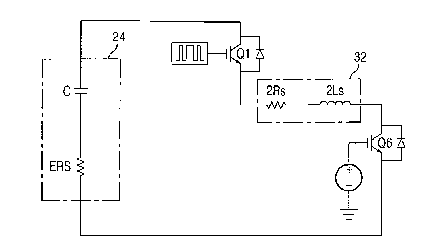
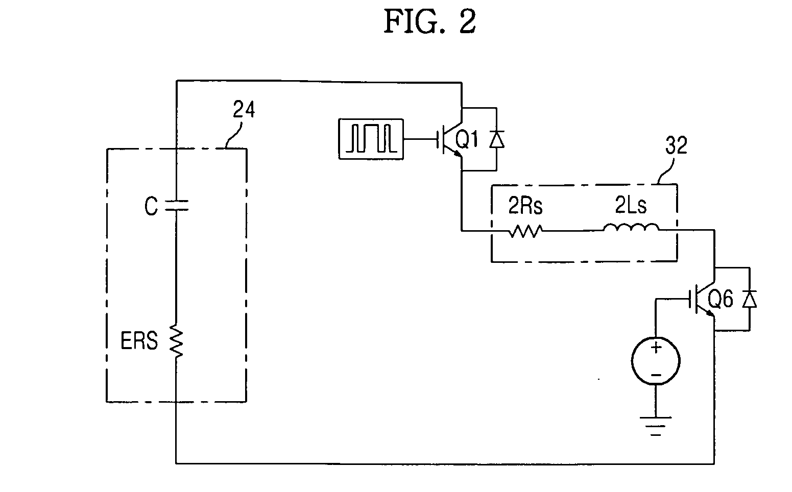
[0011]It is another aspect of the invention to provide an apparatus and method to detect failure of a smoothing electrolytic capacitor, which can detect failure of the smoothing electrolytic capacitor in real time by estimating ESR and C values of the smoothing electrolytic capacitor through a switching operation to detect failure of the smoothing electrolytic capacitor in a discharge duration of the smoothing electrolytic capacitor.

Problems solved by technology

When the smoothing electrolytic capacitor has failed due to deterioration, it causes overheating, resulting in breakdown of its neighboring parts or accidents such as fire.
However, to detect the surface voltage of the smoothing electrolytic capacitor, this smoothing electrolytic capacitor diagnosis method requires that additional voltage measuring means (for example, wires) be attached to the surface of the smoothing electrolytic capacitor, thereby lowering the PCB productivity and increasing the manufacturing costs.

Method used


Image

  • Apparatus and method to detect failure of smoothing electrolytic capacitor
  • Apparatus and method to detect failure of smoothing electrolytic capacitor
  • Apparatus and method to detect failure of smoothing electrolytic capacitor

Examples


Embodiment Construction

[0040]Reference will now be made in detail to the embodiments of the present invention, examples of which are illustrated in the accompanying drawings, wherein like reference numerals refer to the like elements throughout. The embodiments are described below to explain the present invention by referring to the figures.

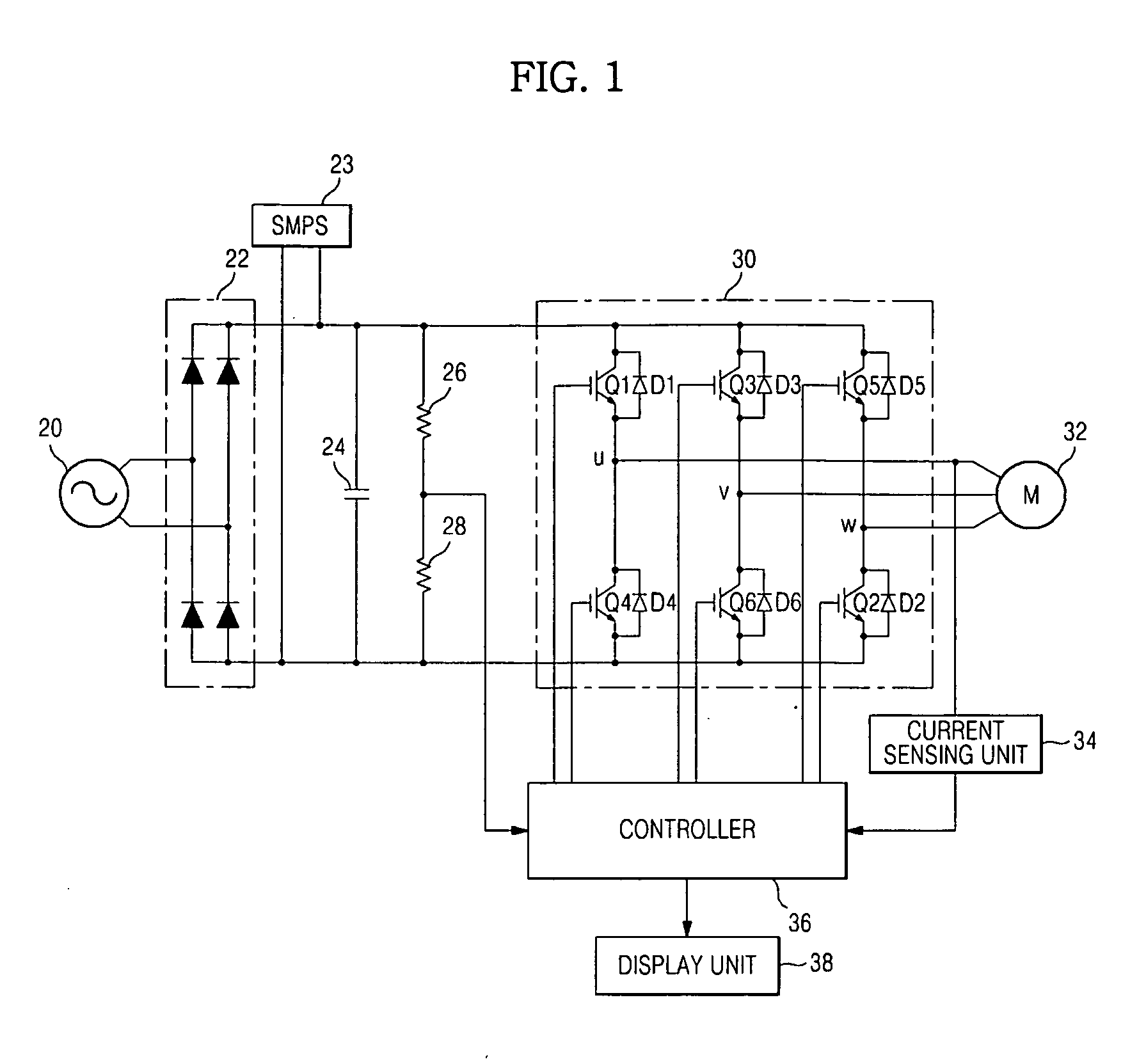
[0041]FIG. 1 is a circuit diagram of an inverter circuit to drive a motor according to an embodiment of the invention.

[0042]As shown in FIG. 1, the inverter circuit, which detects failure of an electrolytic capacitor that smoothes an inverter DC voltage according to the invention, includes a rectifier 22, a switching mode power supply (SMPS) 23, a smoothing electrolytic capacitor 24, voltage divider resistors 26 and 28, an inverter 30, a motor 32, a current sensing unit 34, a controller 36, and a display unit 38. The rectifier 22 rectifies an AC power supply voltage 20 of 220V, 60 Hz or the like. The SMPS 23 is connected to the rectifier 22 to supply a control DC volta...


PUM


Abstract

An apparatus and method to detect failure of an electrolytic capacitor that smoothes a DC voltage in an inverter circuit. The apparatus detects failure of a smoothing electrolytic capacitor in a motor drive inverter circuit that rectifies and smoothes an AC voltage through a rectifier and the smoothing electrolytic capacitor and converts a rectified and smoothed DC voltage into a 3-phase voltage to drive a motor. The apparatus includes a voltage meter, a current sensing unit, and a controller. The voltage meter measures a DC voltage of an inverter when the motor is not in operation. The current sensing unit measures a phase current of the motor when the motor is not in operation. The controller estimates an ESR value of the smoothing electrolytic capacitor from the DC voltage of the inverter and the motor phase current to detect failure of the smoothing electrolytic capacitor.

Description

CROSS-REFERENCE TO RELATED APPLICATIONS[0001]This application claims the benefit of Korean Patent Application No. 2007-0094484, filed on Sep. 18, 2007 in the Korean Intellectual Property Office, the disclosure of which is incorporated herein by reference.BACKGROUND[0002]1. Field[0003]The present invention relates to an apparatus and method to detect failure of an electrolytic capacitor that smoothes DC voltage in an inverter circuit.[0004]2. Description of the Related Art[0005]Inverter circuits are power converters to convert a DC voltage into a 3-phase AC voltage (U, V, W) at any variable frequency. Due to high energy efficiency and easy output control, inverter circuits are widely used to drive motors employed in electrical products such as washing machines, refrigerators, air conditioners, microwave ovens, and elevators.[0006]A DC voltage smoothing electrolytic capacitor is provided at a portion in the inverter circuit which rectifies and smoothes an input (AC) voltage into a DC ...

Claims


Application Information

Patent Timeline
IPC IPC(8): G01R31/12
CPCG01R31/42G01R31/028G01R31/64G01R31/00H01G13/00
Inventor KIM, MYUNG CHULCHOI, JAE YOUNGYOON, JANG HOLEE, SONG BINLEE, KWONG WOON
Owner SAMSUNG ELECTRONICS CO LTD
Learn More