
Image processing apparatus and image processing method

Active Publication Date: 2009-03-19
HISENSE VISUAL TECH CO LTD
View PDF11 Cites 25 Cited by
  • Summary
  • Abstract
  • Description
  • Claims
  • Application Information

AI Technical Summary

Benefits of technology

[0008]In view of such circumstances, it is an object of the invention to provide an image processing apparatus which achieves resolution enhancement to provide sharp and high-quality images and an image processing method.
[0010]According to the invention, the resolution enhancement process suitable for the respective regions is enabled, and a sharp and high-quality high-resolution image is obtained.

Problems solved by technology

In the multi-frame deterioration inverse conversion method, there is a problem that the quality of high-resolution image may be deteriorated because there are cases that the pixel values are modified by the sample values detected by wrong corresponding positions, and that noise component in a flat area is modified sharply.

Method used


Image

  • Image processing apparatus and image processing method
  • Image processing apparatus and image processing method
  • Image processing apparatus and image processing method

Examples


first embodiment

[0045]Referring to FIG. 1 to FIG. 15 and FIG. 30 to FIG. 32, an image processing apparatus according to a first embodiment of the invention will be described below.

(1) Configuration of Image Processing Apparatus

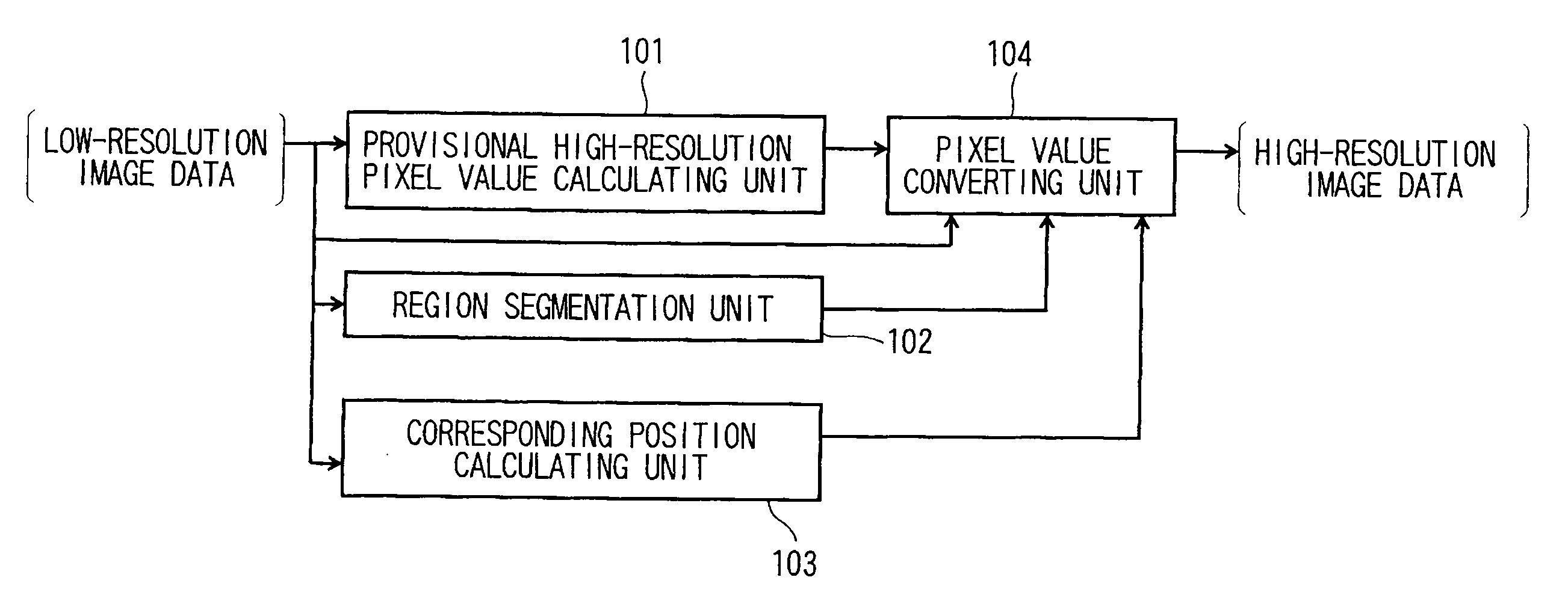
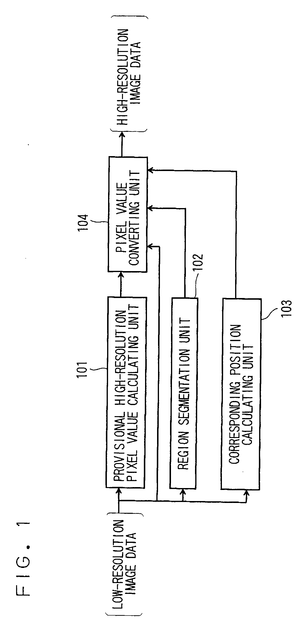
[0046]FIG. 1 is a block diagram of the image processing apparatus according to the first embodiment.

[0047]As shown in FIG. 1, the image processing apparatus includes a provisional high-resolution pixel value calculating unit (hereinafter, referred to as pixel value calculating unit) 101, a region segmentation unit 102, a corresponding position calculating unit 103 and a pixel value converting unit 104.

[0048]The functions of the respective units 101 to 104 can be implemented, for example, by a program embedded in LSI. In other words, they can be implemented by an apparatus which is capable of carrying out parallel processing.

(1-1) Pixel Value Calculating Unit 101

[0049]The pixel value calculating unit 101 receives a supply of low-resolution image data in which a plurality of pi...

second embodiment

[0179]Referring now to FIG. 16, the image processing apparatus according to a second embodiment will be described.

[0180]The second embodiment is an example suitable for condition branching process using a PC (Personal Computer) or the like. On the other hand, the image processing apparatus according to the first embodiment is suitable for parallel process using the LSI or the like as described above.

[0181]FIG. 16 is a block diagram showing an image processing apparatus according to the second embodiment.

[0182]In the image processing apparatus according to the second embodiment, area information from the region segmentation unit 102 is supplied to a corresponding position calculating unit 1603, then the corresponding position calculating unit 1603 selects the entered area information and calculates the corresponding positions, and a pixel value converting unit 1604 converts pixel values without using the area information.

[0183]In other words, the second embodiment is different from t...

third embodiment

[0187]Referring now to FIG. 17 and FIG. 18, the image processing apparatus according to a third embodiment of the invention will be described.

[0188]According to the first embodiment, the description has been given on the moving image data. The third embodiment may be applied to a case of a still image having no continuous frames arranged in sequence like the case of the moving image.

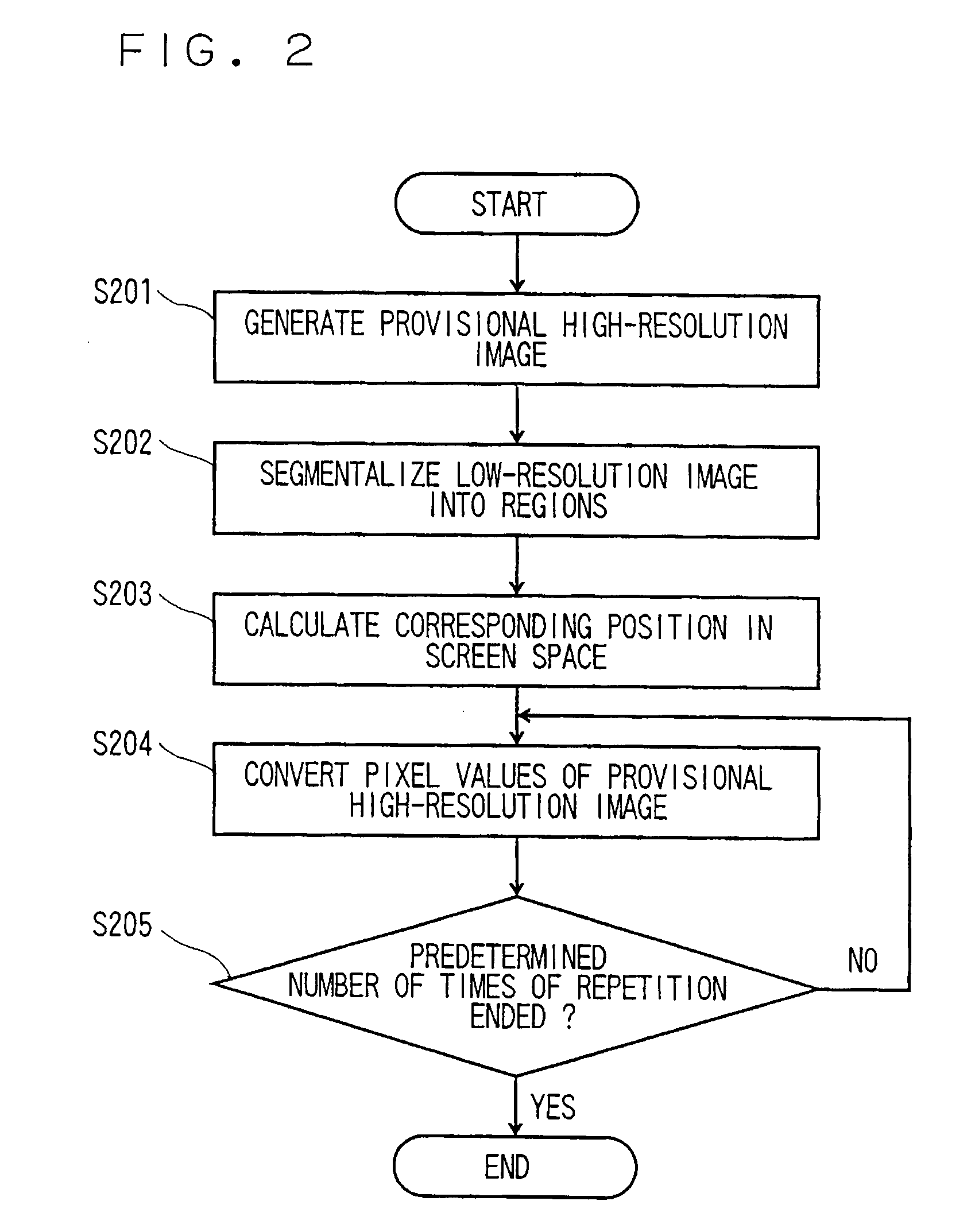
[0189]The third embodiment is applied to a case in which self congruity in the frame of a shooting image (in a reference frame) is utilized as operation to calculate the corresponding positions in the screen space by the corresponding position calculating units 103, 1603 in FIG. 1 and FIG. 16 in Step S203 in FIG. 2.

[0190]FIG. 17 is a graph of an actual digital image data, in which the lateral axis represents the lateral coordinates of a pixel, and the vertical axis represents the pixel value indicating luminance. Here, different five rows of data in the same frame are shown by separate sequential lines. ...


PUM


Abstract

An image processing apparatus calculates estimated pixel values of respective pixels of a provisional high-resolution image by interpolation on basis of pixel values in a reference frame, segmentalizes interior of the reference frame into an edge region, a texture region or a flat region and other on basis of pixel values of respective pixels, sets the respective pixels in the reference frame as target pixels one by one in sequence, calculates corresponding positions on the provisional high-resolution image, of the respective target pixels in fractional pixel accuracy on basis of information on the segmented regions including the target values, modifies the estimated pixel values so that difference from the pixel values of the target pixels to provisionally estimated pixel values obtained from the estimated pixel values of the provisional high-resolution image for pixels around the corresponding positions of the target pixels, becomes smaller, and obtains modified pixel values.

Description

CROSS-REFERENCE TO RELATED APPLICATIONS[0001]This application is based upon and claims the benefit of priority from the prior Japanese Patent Application No. 2007-237645, filed on Sep. 13, 2007; the entire contents of which are incorporated herein by reference.BACKGROUND OF THE INVENTION[0002]1. Field of the Invention[0003]The present invention relates to an image processing apparatus which enhances the resolution of a low-resolution image and an image processing method.[0004]2. Description of the Related Art[0005]Recently, high-resolution televisions or displays having a large number of pixels are in widespread use. The televisions or displays convert the number of pixels of an image data into the number of pixels of a panel when displaying an image. Interpolation in which filtering is carried out with Sinc function based on the sampling theorem (cubic convolution, BiCubic method, etc.) when applying a resolution enhancement process, and a multi-frame deterioration inverse conversi...

Claims


Application Information

Patent Timeline
IPC IPC(8): G06T3/40G06T3/00G06T5/50H04N1/387
CPCG06T3/4007
Inventor MATSUMOTO, NOBUYUKIIDA, TAKASHIKANEKO, TOSHIMITSUTAKESHIMA, HIDENORITAGUCHI, YASUNORI
Owner HISENSE VISUAL TECH CO LTD
Learn More