System and method for selectively rejecting frequency bands in wireless communication systems

Inactive Publication Date: 2009-03-19
COMMSCOPE TECH LLC +1
View PDF4 Cites 30 Cited by
  • Summary
  • Abstract
  • Description
  • Claims
  • Application Information

AI Technical Summary

Benefits of technology

[0006]The present invention provides a system and method for selectively rejecting frequency bands in wireless communication systems. For at least one example embodiment, the system and method provide a software-selective band rejection technique using multiple cascaded band rejection filters that can remove undesired sub-bands within the RF pass band of the wireless communication system, subsystem or network involved. Thus, the present invention enables the remaining or desired sub-bands in that RF pass band to be passed. Consequently, the software-oriented band rejection approach of the present invention enables an operator or user to rapidly configure or reconfigure its designated bands or sub-bands (e.g., on an application-by-application basis) without having to procure and install new bandpass filter hardware or other filter hardware.

Problems solved by technology

A significant problem with the allocation of frequency spectrum in existing mobile radiotelephone or cellular communication systems is that the sub-bands assigned to the network operators are typically not contiguous.
Consequently, this lack of sub-band standardization causes the design and configuration of existing mobile radiotelephone or cellular communication networks to be inflexible, and also costly if one or more of a network operator's sub-band allocations are changed and the network has to be reconfigured to accommodate such a change.
However, if an operator has to add or subtract one or more sub-bands to or from an existing network configuration, then the operator has to procure and install one or more new bandpass filters to accommodate such a change.
This hardware-oriented bandpass filter approach is costly and also results in decreased operating time.

Method used


Image

  • System and method for selectively rejecting frequency bands in wireless communication systems
  • System and method for selectively rejecting frequency bands in wireless communication systems
  • System and method for selectively rejecting frequency bands in wireless communication systems

Examples


Embodiment Construction

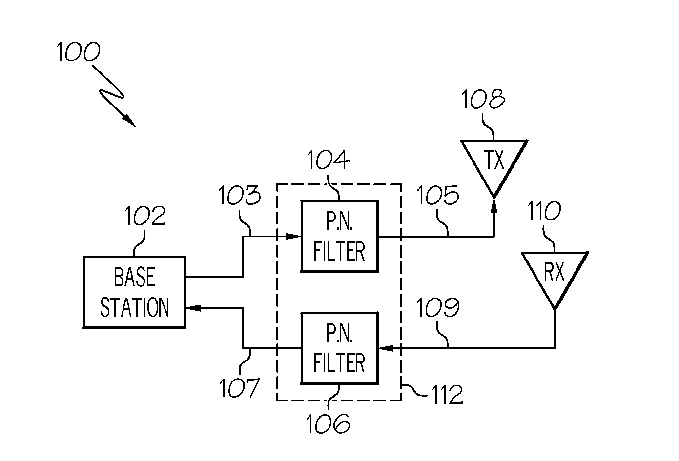
[0011]With reference now to the figures, FIG. 1 depicts a block diagram of an example wireless communication system 100, which can be used to implement one or more embodiments of the present invention. For at least one example embodiment, system 100 may be used to implement a mobile radiotelephone or cellular communication system including a network configured with a plurality of cells (e.g., macro-cells, micro-cells, pico-cells, or a combination thereof). For example, system 100 may be used to implement a wireless communication system including a network operated in accordance with one of the known telecommunications network protocols, such as the protocol for the Global system for Mobile Communications (GSM), Advanced Mobile Phone System (AMPS), Digital-AMPS (D-AMPS), Code Division Multiple Access (CDMA), Wideband CDMA (WCDMA), Time Division Multiple Access (TDMA), Cellular Digital Packet Data (CDPD), Enhanced Data rates for GSM Evolution (EDGE), General Packet Radio Service (GPRS...


PUM


Abstract

A system and method for selectively rejecting frequency bands in wireless communication systems are disclosed. For example, the system provides a software-selective band rejection technique using multiple cascaded band rejection filters that can remove undesired sub-bands within the RF pass band of the wireless communication system, subsystem or network involved. Thus, the system enables the remaining or desired sub-bands in that RF pass band to be passed. Consequently, the software-oriented band rejection approach enables a designer, operator or user to rapidly configure or reconfigure its designated bands or sub-bands (e.g., on an application-by-application basis) without having to procure and install new bandpass filter hardware or other filter hardware.

Description

FIELD OF THE INVENTION[0001]The present invention relates generally to the wireless communications field, and more specifically, but not exclusively, to a system and method for selectively rejecting frequency bands in wireless communication systems.BACKGROUND OF THE INVENTION[0002]In certain wireless communication systems, such as for example, mobile radiotelephone or cellular communication systems, the available radio spectrum is designated for use by network operators in specific frequency bands. For example, there are eight frequency bands allocated for use by network operators in the Global System for Mobile Communications (GSM). Specifically, the GSM-850 and GSM-1900 bands are the primary bands designated for use by GSM network operators in the United States, Canada and parts of South and Central America, and the GSM-900 and GSM-1800 bands are the primary bands designated for use by GSM network operators in other parts of the world. As other examples, there are ten frequency ba...

Claims


Application Information

Patent Timeline
IPC IPC(8): H04Q7/20
CPCH04B1/0475H04B1/50H04B1/18
Inventor HERMEL, MICHAEL J.
Owner COMMSCOPE TECH LLC
Why Eureka
Try Eureka