Biological Sensor System

a biosensor and sensor technology, applied in the field of biosensor systems, can solve the problems of high cost, inconvenient operation, and inability to fully scan an entire microarray, and achieve the effect of high cos

Inactive Publication Date: 2009-03-19
III N TECH
View PDF11 Cites 9 Cited by
  • Summary
  • Abstract
  • Description
  • Claims
  • Application Information

AI Technical Summary

Benefits of technology

[0010]However, so far, deep UV light of shorter than 280 nm in wavelength has been obtained from the output of a frequency-tripled mode-locked Ti:Sapphire Laser. Thus,

Problems solved by technology

Laser scanners can scan images with excellent spatial resolution, but due to their nature, can only scan pixels individually and scanning an entire micro-array still takes a long time to complete, due to the vast number of DNA probes involved.
A filtered lamp together with a CCD camera, on the other hand, can scan an entire micro-array more quickly, but spatial resolution becomes hindered due to crosstalk, which is the interference between neighboring testing spots.
DNA micro-arrays based on current technologies are also bulky and expensive due to the use of discrete component systems (DNA micro-array, light source, and detector), which limits the ability of wide spread use of DNA micro-

Method used


Image

  • Biological Sensor System
  • Biological Sensor System
  • Biological Sensor System

Examples


embodiment 800

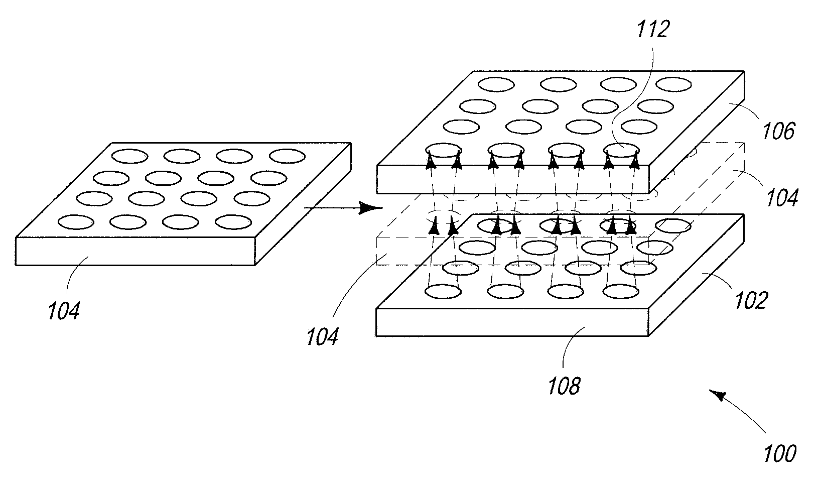
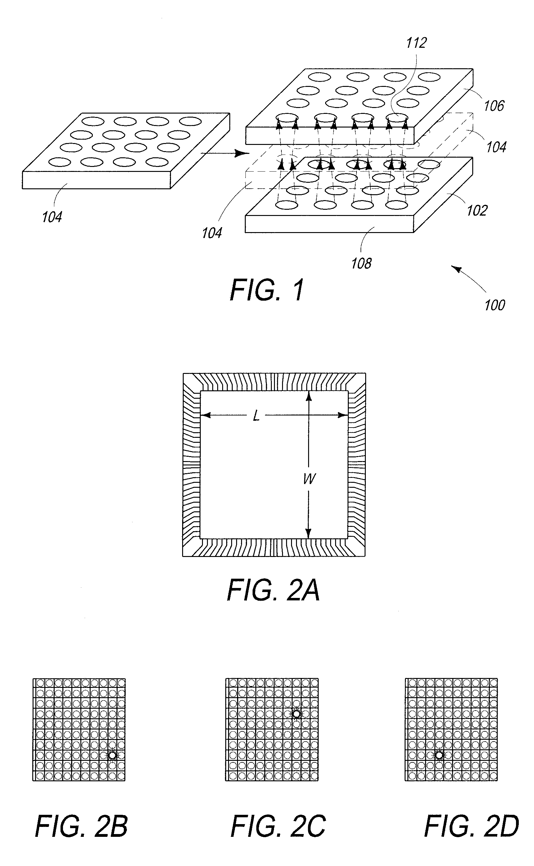
[0047]Referring to FIG. 8, yet another sensor embodiment 800 is shown. In this embodiment, discrete samples of biological material to be tested, e.g., sample tagged DNA or protein sequence 802, are deposed directly (e.g., printed) onto each individual micro-emitter, e.g., emitter 804. In this embodiment, an InAlGaN micro-emitter array is fabricated onto a sapphire, silicon, or silicon carbide substrate used. Like in past embodiments, each emitter (e.g. micro-emitter 804) and sample (e.g., biological material 802) is associated with and caused to be located directly underneath a particular detector in a detector array or CCD pixel 808 which are a component of an ROIC 810. The micro-emitter array used here has essentially the structures as those described for the embodiments of FIG. 6 or FIG. 7. The FIG. 8 device is different from the FIG. 6 and FIG. 7 embodiments in that the replaceable DNA or protein microarray substrate is removed, and the sample array is directly formed on the top...

embodiment 900

[0048]Referring to FIG. 9, an embodiment 900 is disclosed in which the DNA or protein micro-array (not shown, but at positions 902) is directly constructed onto or into a sapphire substrate 904. The micro-emitter array 906 in this embodiment is deposed onto the saphire substrate 904, then flipped relative to the detector / CCD array on the ROIC 908. Thus, the micro-emitter array and its driving circuit are enclosed with only the sapphire substrate backside exposed. In embodiments, this backside has etched wells 902 used for DNA or protein attachment. The enclosure of micro-emitter array ensures that the illumination features will not be exposed to the materials introduced, and therefore, that the sapphire surface will be reusable. The micro-emitter array 906 here has the same structures of the embodiments of FIG. 6 or FIG. 7. The difference here is that the replaceable DNA or protein microarray substrate is removed, and the sample array is directly formed on the reverse side of the tr...


PUM


Abstract

Disclosed is a system using each of the descrete emitters in a III-nitride micro-emitter array as a light source for measuring the properties of independent samples of biological materials deposed on a micro-array using some form of detecting device, e.g, a detector array or charge-coupled device. In embodiments the emitter array produces deep ultraviolet in investigating protein-protein interactions or to detect biological and chemical molecules with high specificity by monitoring changes in a protein's intrinsic fluorescence.

Description

CROSS-REFERENCE TO RELATED APPLICATIONS[0001]This application claims the benefit of U.S. Provisional Patent Application No. 60 / 972,273 filed Sep. 14, 2007, the entire disclosure of which is herein incorporated by reference.BACKGROUND OF THE INVENTION[0002]1. Field of the Invention[0003]The invention relates generally to the field of biological testing. More specifically, the invention relates to the field of using detectors to evaluate arrays of biological materials which have been subjected to some form of electromagnetic radiation.[0004]2. Description of the Related Art[0005]One area of related art is in the field of DNA testing applications. Recently, a great deal of attention has been focused on the research and development of micro-array or micro-assay techniques, which use an array of DNA or protein related probes, also known as “spots,” which are biological materials deposited robotically using techniques adapted from the semiconductor industry, or printed using ink-jet print...

Claims


Application Information

Patent Timeline
IPC IPC(8): C40B60/12
CPCB01J2219/00317B01J2219/00441B01J2219/00527B01J2219/00605C40B60/12B01J2219/00659B01J2219/00702B01J2219/00722B01J2219/00725B01J2219/00612
Inventor JIANG, FRANK YUEFAN, ZHAOYANG
Owner III N TECH
Why Eureka
Try Eureka