
Load Control Device and Method Thereof

a control device and load technology, applied in the field of scheduling requests, can solve the problems of high volume of meaningless, difficulty in reducing and the inability to process extremely high traffic, so as to reduce the load of the device manager and avoid the performance degradation of the server

Active Publication Date: 2009-03-19
NIPPON TELEGRAPH & TELEPHONE CORP
View PDF17 Cites 160 Cited by
  • Summary
  • Abstract
  • Description
  • Claims
  • Application Information

AI Technical Summary

Benefits of technology

[0025]In view of the background described above, it is an object of the present invention to provide a load control device and a method thereof that can avoid the performance degradation of a server when too many requests are received.

Problems solved by technology

As the Web services become increasingly popular, the problems to be solved for using the services smoothly are becoming apparent.
One of those problems is how to process extremely high traffic caused by the concentrated use of services.
A high volume of meaningless requests such as F5 attacks are sometimes sent by a malicious client.
Too many requests, if sent due to those factors, degrade the request processing performance of the server.
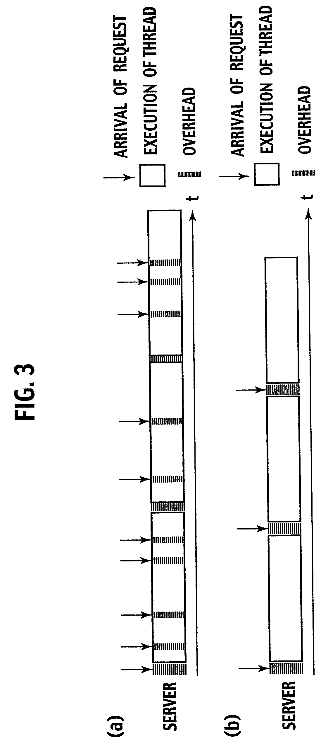
The following are the factors that degrade the server's request processing performance during extremely high traffic times. First, the input / output overhead, such as interrupts and TCP / IP processing, is increased when the server receives too many requests to process.
Second, the number of threads or processes for processing requests is increased and, as a result, the context switching overhead, which is an overhead required for switching threads and processes, becomes obvious.
Third, because the response time until a response is returned to a client is increased, clients that cannot wait long are forced to cancel their requests.
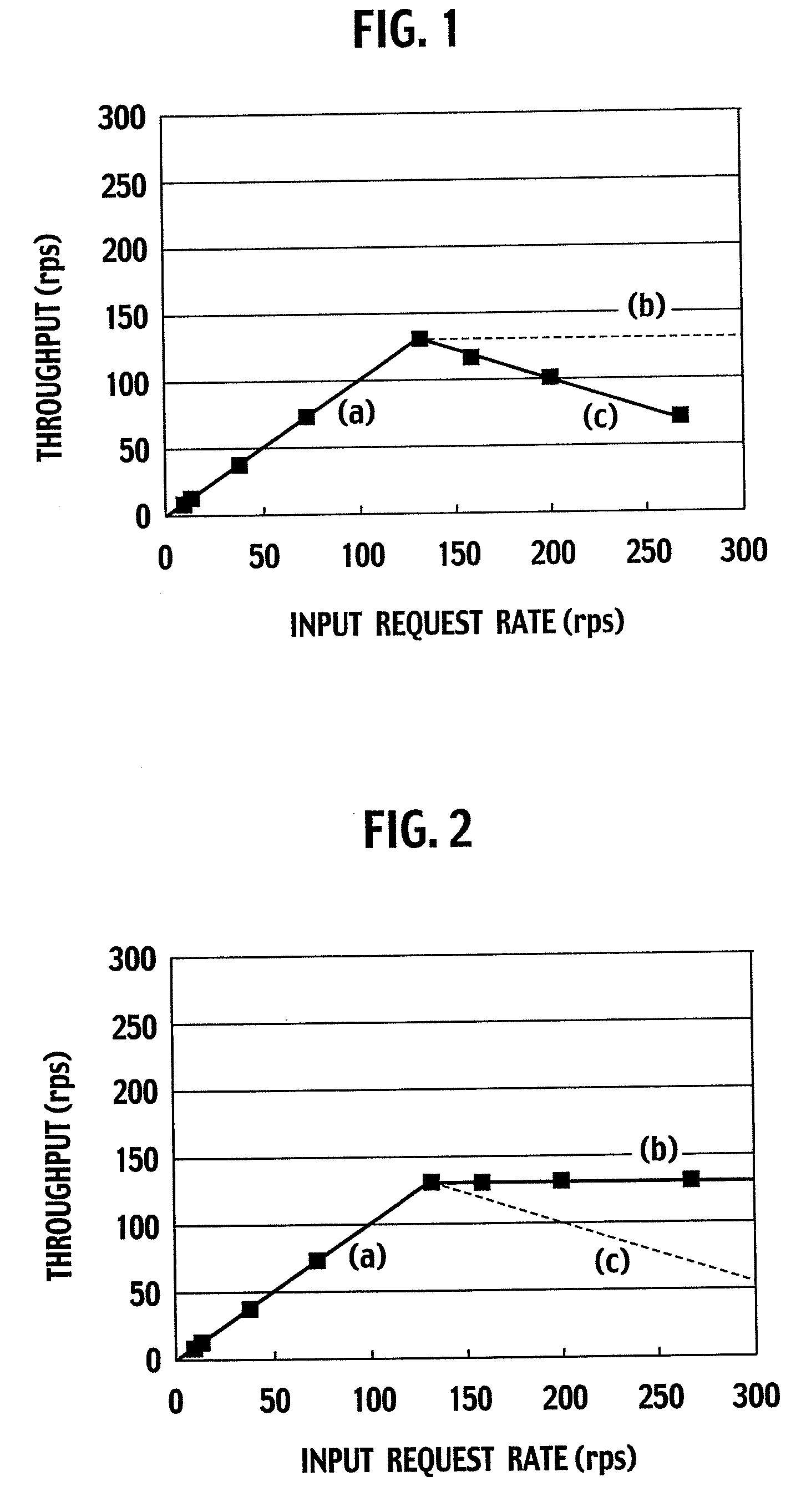
As a result of those factors, the problem that is generated is that the processing performance of the server is degraded as the server becomes more and more congested.
FIG. 1 shows the experimental result showing a decrease in the processing performance of a Web server when the Web server receives too many requests.
Because of this, a problem is generated that a new TCP connection cannot be established because the server becomes overloaded before the number of TCP connections reaches the upper limit or, conversely, because the number of TCP connections reaches the upper limit even if the server resources are available.
However, because the traffic control is performed after it is determined that the server is overloaded, a temporary decrease in the server performance cannot be avoided.
However, the bandwidth cannot be used as the index for accurately measuring the load on the server.
So, it is difficult to absolutely avoid the overload by limiting the bandwidth while fully utilizing the resources of the server.
However, even if the degree of parallelism is controlled on the server, the overhead of interrupts or TCP / IP processing, which is the primary cause of request-processing performance degradation and which is involved in the reception of too many requests for the server to process, cannot be avoided.
The result is that the processing performance of the server is degraded as with other methods during extremely high traffic times. Another problem is that, because the HTTP server or the Web application must be changed, it is difficult to introduce this method into the services already in operation.
Because of this, the problem is that the concentration of RTSP requests on a stream server increases the overhead for processing requests and degrades the processing performance of the stream server.
In this case, an overhead that is generated when the server receives too many requests to process is not generated.
In addition, there is no spare time in the server from the moment the processing is completed to the moment the next request arrives.

Method used


Image

  • Load Control Device and Method Thereof
  • Load Control Device and Method Thereof
  • Load Control Device and Method Thereof

Examples


first embodiment

[0088]A first embodiment of the present invention will be described with reference to the drawings.

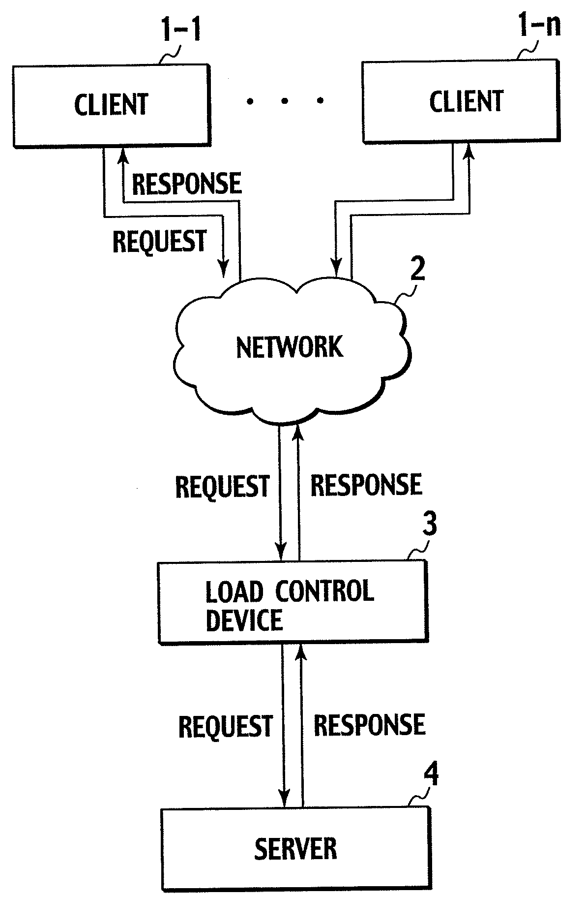
[0089]FIG. 5 is a block diagram showing the first embodiment of the present invention. The present invention comprises clients 1-1 to 1-n that issue requests, a server 4 that returns a response corresponding to a request, and a load control device 3 that relays requests and responses. The server 4 may be a software module such as Apache or may be a hardware module whose physical resources such as a CPU and a memory are independent of the load control device 3. This load control device 3 may be connected to two or more servers 4 to allow one load control device 3 to control the load of multiple servers 4. In addition, the load control device 3 may be created by extending the existing technologies, such as a reverse proxy, a Web accelerator, a Firewall, and a load balancer. The load control device 3 monitors the number of requests which are already sent to the server 4 but to which respo...

second embodiment

[0169]Next, a second embodiment will be described in which TCP / IP (Transfer Control Protocol / Internet Protocol) widely used on the Internet is used as the protocol for sending and receiving requests and responses. FIG. 10 is a block diagram showing the second embodiment of the present invention. This embodiment comprises clients 1-1 to 1-n that issue requests, a server 4 that returns a response corresponding to a request, and a load control device 3 that relays requests and responses. The load control device 3 may be created by extending the existing technologies, such as a reverse Proxy, a Web accelerator, a Firewall, and a load balancer.

[0170]A load control system in this embodiment comprises the following seven functional blocks.

[0171]Request receiving unit 30

[0172]Request sending unit 32

[0173]Response receiving unit 34

[0174]Response sending unit 33

[0175]Scheduling unit 31

[0176]The request receiving unit 30 sends a request, received from the clients 1-1 to 1-n, to the scheduling ...


PUM


Abstract

The number of response-waiting requests which are already sent to a server (4) but to which a response is not yet returned from the server (4) is limited. To limit this number, received requests are temporarily accumulated in a buffer if the number of response-waiting requests has reached a threshold and, until the number of response-waiting requests falls below the threshold, requests are not sent from the buffer. The execution status of the server (4) is monitored, and the threshold is increased when the response time from the server (4) to a request is within an allowable range, and the threshold is decreased when the response time exceeds the allowable range. In addition, TCP connections between a load control device (3) and clients (1-1, 1-n) are aggregated so that the number of simultaneous connections of TCP connections between the server (4) and the load control device (3) becomes equal to or smaller than the threshold of the number of response-waiting requests.

Description

TECHNICAL FIELD[0001]The present invention is used for a device provided between a client and a server to transfer a request, received from the client, to the server and to transfer a response, returned from the server in response to the request, to the client. More particularly, the present invention relates to the scheduling of a request. Although focus is on a Web server in this specification, this specification does not necessarily limit the application of the present invention to other servers.BACKGROUND ART[0002]Widespread use of the Internet allows the user to use various services via a network. Examples include mail, homepage browsing, search, online commerce, IP phones, and video on demand. Those network services may be provided in various forms and, recently, the use of a Web server has become a mainstream of the interface with clients.[0003]The basic mechanism of services (Web services) using a Web server is as follows. First, a client sends a request, which specifies a U...

Claims


Application Information

Patent Timeline
IPC IPC(8): G06F15/173
CPCG06F9/4843H04L47/10H04L47/193H04L47/27H04L47/39H04L43/16H04L67/32H04L69/165H04L41/0896H04L43/0894H04L69/16H04L67/60
Inventor KUREBAYASHI, RYOSUKEISHIDA, OSAMUOTA, SATORUHAYASHI, TSUNEMASAOBANA, KAZUAKI
Owner NIPPON TELEGRAPH & TELEPHONE CORP
Learn More