Gas separator and gas separating method

Inactive Publication Date: 2009-03-26
YOSHIDA
View PDF7 Cites 8 Cited by
  • Summary
  • Abstract
  • Description
  • Claims
  • Application Information

AI Technical Summary

Benefits of technology

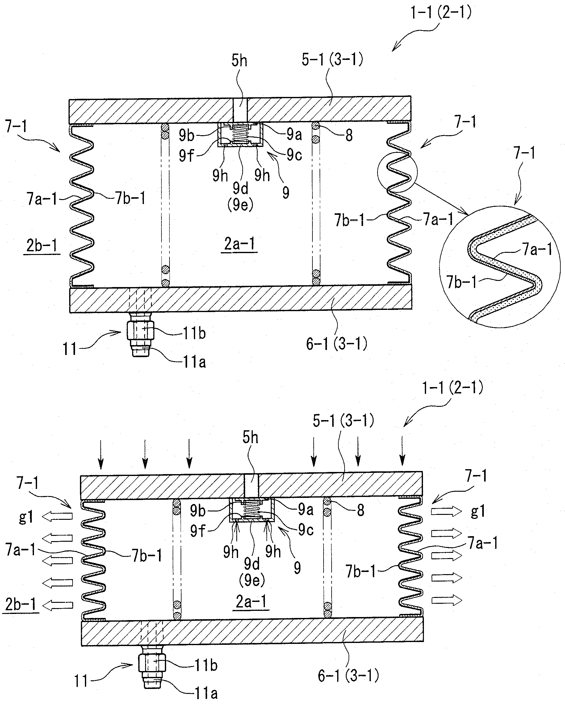
[0087]According to the separating device of claim 39, in addition to the operational effect of the gas separating device of claim 38, an oxygen enriched gas (gas g1) which is taken out via the one check valve, and an oxygen enriched gas (gas g1) which is taken out via the other check valve can be sequentially supplied to a human body via the gas supply tool. An oxygen enriched gas can be supplied to those who require oxygen inhalation due to disease and injury, those who immediately after vigorous workout, those who are in the places under oxygen-deficient atmosphere as in the summits of high mountains and the like. Since a gas can be taken out by the movement in both the forward direction and the returning direction as described in the explanation of the operational effect of the separating device of claim 33, the gas can

Problems solved by technology

However, since each of the conventional gas separating devices requires a compressor, the entire device generally increases in size and weight.
There is also the problem in the respect that the structure

Method used


Image

  • Gas separator and gas separating method
  • Gas separator and gas separating method
  • Gas separator and gas separating method

Examples


sixth modification example

(Sixth Modification Example of Gas Separating Device)

[0143]Referring to FIGS. 13 to 15, a gas separating device 1-6 according to a sixth modification example will be described. FIG. 13 is a plane view of the gas separating device 1-6, and FIGS. 14 and 15 are sectional views taken along the line C-C of the gas separating device 1-6 shown in FIG. 13. The gas separating device 1-6 includes an airtight container 45 with an inside and an outside partitioned by a partition wall 44, and the airtight container 45 is constructed to be capable of housing a stored material such as food therein. Namely, the partition wall 44 is generally constructed by a lower container 46 with an upper end opened, and an upper container 47 with a lower end opened, and a lid body 49, and all the members are composed of a synthetic resin as the main material. The lower container 46 is generally constructed by a bottom part 46a and a peripheral wall 46b which is raised from a peripheral edge of the bottom part 46...

seventh modification example

(Seventh Modification Example of Gas Separating Device)

[0147]Referring to FIG. 16, a gas separating device 1-7 according to a seventh modification example will be described. FIG. 16 is a sectional view of the gas separating device 1-7. The gas separating device 1-7 includes an airtight container 22-7 with an inside and an outside partitioned by a partition wall 21-7. The partition wall 21-7 is constructed by including a cylindrical fixed partition wall 23-7 having an airtight chamber 23-7, a movable partition wall 25-7 which is inside the airtight chamber 24-7 and reciprocatingly slidable in the lengthwise direction (lateral direction in FIG. 16) of the airtight chamber 24-7 with respect to an inner peripheral surface 23e-7 of the fixed partition wall 23-7. Reciprocating sliding of the movable partition wall 25-7 is performed by a drive structure (not shown in the drawing). The fixed partition wall 23-7 is constructed by an annular peripheral wall 23b-7 entirely composed of a metal ...


PUM

PropertyMeasurementUnit
Forceaaaaaaaaaa
Pressureaaaaaaaaaa
Gas permeabilityaaaaaaaaaa

Abstract

There is provided a gas separating device which is capable of being made compact and light. A part of an airtight container (2) is constructed by a gas separating membrane (13), and a gas separating membrane (13) is constructed to be able to separate and discharge at least a part of a gas g1 included in a gas G to the outside of the airtight container (2) from the gas G. A gas outlet valve is constructed to allow the inside of the airtight container and the outside to communicate with each other to be able to discharge a gas g2 remaining in the inside of the airtight container (2) to the outside when the total pressure of the inside of the airtight container (2) becomes P2 (P2>P1).

Description

BACKGROUND OF THE INVENTION[0001]1. Field of the Invention[0002]The present invention relates to a gas separating device and a gas separating method for separating a gas by a pressure difference caused between one side and the other side partitioned by a gas separating membrane.[0003]2. Description of the Related Art[0004]As a gas separating device using a gas separating membrane, there are the ones disclosed in Patent Documents 1 to 3. Each of the gas separating devices disclosed in Patent Documents 1 to 3 (hereinafter, generally and properly called “conventional gas separating devices”) is constructed so that compressed air is supplied to a nitrogen separating membrane module from an air compressor to separate an oxygen gas and a nitrogen gas by the pressure difference caused between one side and the other side of the nitrogen separating membrane. Each nitrogen gas obtained by separation is used for being charged into automobile tires.[0005][Patent Document 1] Japanese Patent Appl...

Claims


Application Information

Patent Timeline
IPC IPC(8): B01D53/22
CPCA63B39/027A63B41/12B01D53/22B01D2313/50B01D63/08B01D63/10B01D2313/24B01D63/02B01D63/16A23L3/3418B01D53/228
Inventor MORI, AKINORI
Owner YOSHIDA
Why Eureka
Try Eureka