Flexographic Printing Press

a printing press and flexographic technology, applied in the field of flexographic printing presses, can solve the problems of unnecessary installation of three-ring bearings, and achieve the effects of reducing the time required for drying, and reducing the cost of installation

Inactive Publication Date: 2009-03-26
KOENIG & BAUER AG
View PDF16 Cites 11 Cited by
  • Summary
  • Abstract
  • Description
  • Claims
  • Application Information

AI Technical Summary

Benefits of technology

[0011]The use of a synchronous motor and / or of a drive mechanism, with excitation by a permanent magnet as the drive motor for the printing group cylinders or the screen roller, provides a particularly simple, and yet strong drive mechanism for these rotating bodies.
[0012]A dryer is arranged in such a way that the waste heat from the dryer again dries a paper web running over it. Accordingly, the time required for drying, or the path required for drying, is shortened.
[0013]An additional advantage is provided because of the coupling of the chamber doctor blade with the linear bearing of the screen roller. It is advantageous, in connection with a hydraulic engagement of the doctor blade system, in contrast to a pneumatic engagement, that the hydraulic pressure column is not compressible. However, it is disadvantageous with this embodiment, that a rapid disengagement of the doctor blade chamber from the screen roller is not possible in the case of a required position change of the screen roller, for example because of a paper rip. By use of the coupling with the linear carriage of the screen roller, which is provided in accordance with the present invention, this disadvantage is avoided.
[0014]In accordance with further embodiments of the present invention, it is possible to print at variable section lengths, from which a particularly efficient possibility for operating the flexographic printing press results.
[0015]In accordance with a further aspect of the present invention, it is contemplated to clear the surface of a screen roller, by suction, prior to the entry of the screen roller into the chamber doctor blade. Because of this, the print quality, in particular, of the press can be improved and dirt accumulation can be reduced.
[0016]In accordance with a further aspect of the present invention, the possibility is provided of making the imprinting of paper webs of different widths possible in a simple manner.

Problems solved by technology

The expensive installation of three-ring bearings is unnecessary.

Method used


Image

  • Flexographic Printing Press
  • Flexographic Printing Press
  • Flexographic Printing Press

Examples


Embodiment Construction

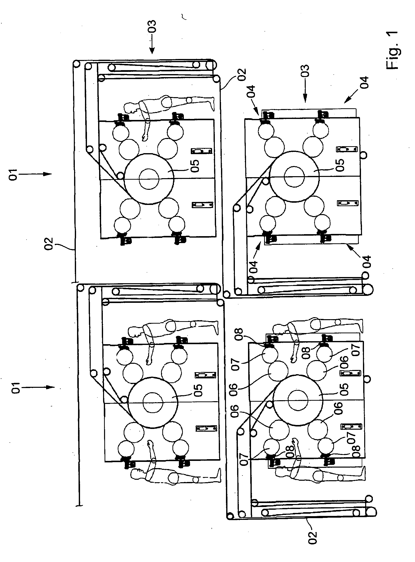
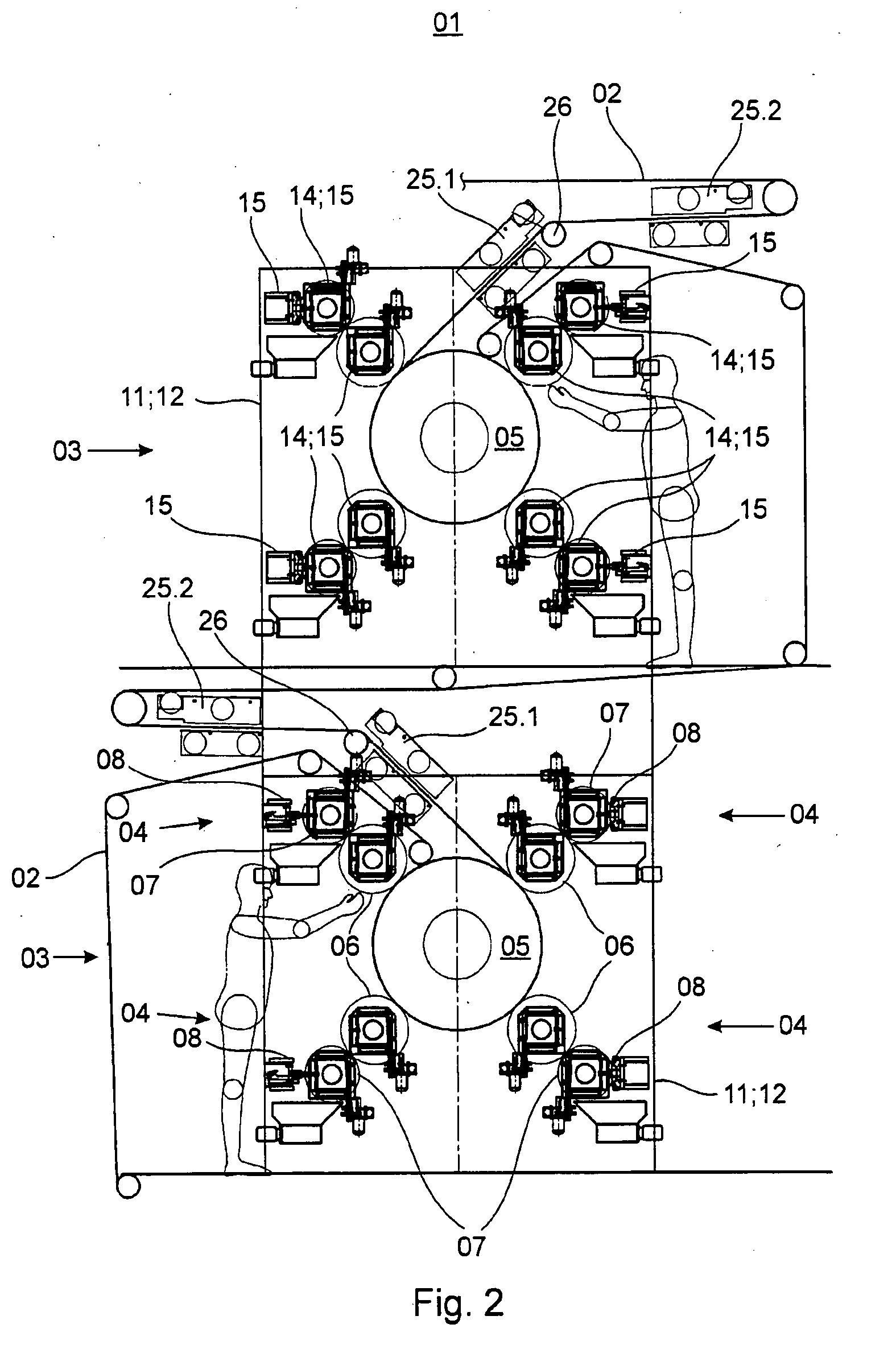
[0051]Referring initially to FIGS. 1 and 2, there may be seen a schematic representation of aflexographic printing press, which is not shown in further detail. The depicted flexographic printing press comprises several, such as, for example, two, side-by-side arranged printing towers 01, each of which printing towers 01 has several, and in particular has two, printing units 03, and in particular has two, satellite printing units 03, arranged on top of each other, and through which satellite printing units 03, imprint material webs 02, and in particular paper webs 02, are conducted for being imprinted on both sides in several colors. The printing towers 01 can be arranged on a machine pedestal, which is not specifically represented, and roll changers, which are also not specifically represented, can be arranged underneath the pedestal. Such roll changers supply the printing towers 01 with paper webs 02 in a generally conventional manner. The paper webs 02 pass through the printing to...


PUM


Abstract

A flexographic printing press is comprised of at least four printing cylinders which are each driven by a respective drive motor. These at least four printing cylinders cooperate directly with a common satellite cylinder during the printing of a web of material. Each of these printing cylinders supports at least one flexographic printing plate. Each end journal of such printing cylinder is mounted in at least one linear bearing that is located on a lateral frame, and which can be moved perpendicularly to the axis of rotation of the respective cylinder. A stator of each driving motor can be moved along with the associated linear bearing, or along with the printing cylinder. Each such drive motor is configured as a synchronous motor which is excited by a permanent magnet. An independent hydraulic actuator is assigned to each printing cylinder, to change the position of that printing cylinder. At least one linear bearing is arranged in a bearing unit which is placed on the interior wall of the respective lateral frame. The journals of each printing cylinder do not penetrate the lateral frames.

Description

CROSS-REFERENCE TO RELATED APPLICATIONS[0001]This application is the U.S. national phase, under 35 USC 371, of PCT / EP2006 / 063027, filed Jun. 8, 2006; published as WO 2006 / 134070 A2 and A3 on Dec. 21, 2006 and claiming priority to DE 10 2005 028 424.8, filed Jun. 17, 2005; to DE 10 2005 032 120.8, filed Jul. 7, 2005; to DE 10 2005 039 074.9, filed Aug. 18, 2005 and to DE 10 2006 003 013.3, filed Jan. 23, 2006, the disclosures of which are expressly incorporated herein by reference.FIELD OF THE INVENTION[0002]The present invention is directed to a flexographic printing press. The flexographic printing press has at least one forme cylinder, which is driven by its own electric motor. At least one flexographic printing plate is carried on the at least one forme cylinder.BACKGROUND OF THE INVENTION[0003]An arrangement for inking a roller of a printing group is known from WO 03 / 047864 A2 and which is usable in connection with an inking system for a printing group of a double-width printing...

Claims


Application Information

Patent Timeline
Patent Type & Authority Applications(United States)
IPC IPC(8): B41F31/00
CPCB41F5/24B41F13/0045B41F13/30B41F31/027H02K11/0021B41P2213/734H02K7/086H02K7/14B41F31/307H02K11/215
Inventor ROTHLEIN, EWALDSCHNEIDER, GEORG
Owner KOENIG & BAUER AG
Why Eureka
Try Eureka