

Temperature regulating member
- Summary
- Abstract
- Description
- Claims
- Application Information
AI Technical Summary
Benefits of technology
Problems solved by technology
Method used
Image

Examples
Embodiment Construction
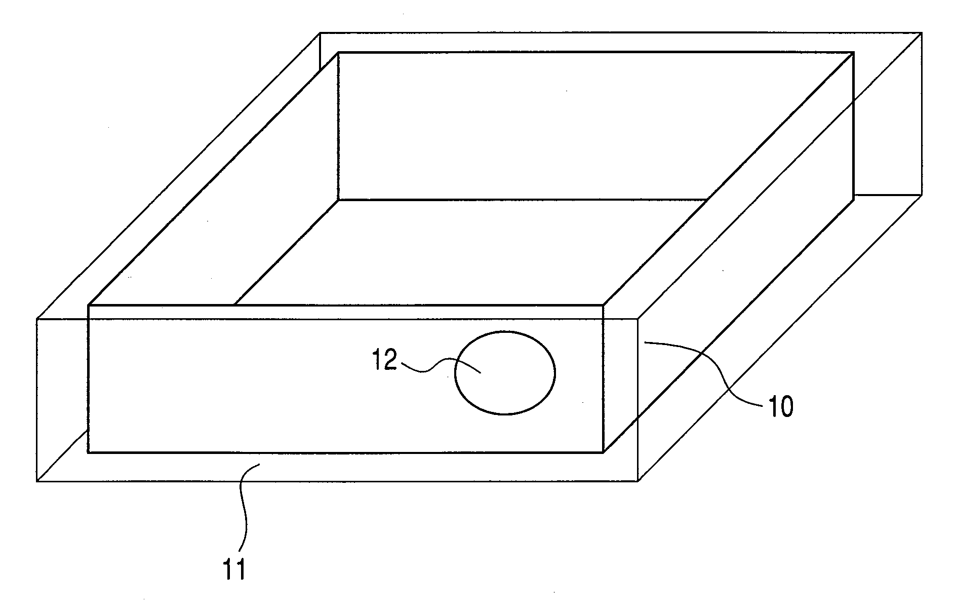
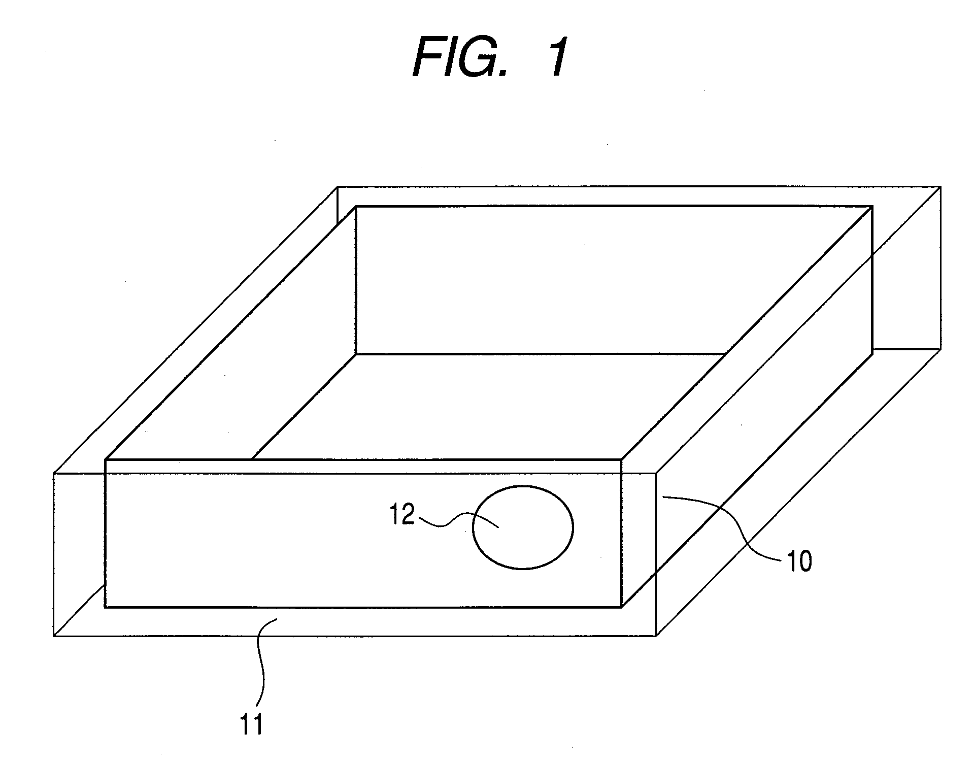
[0026]The embodiments of this invention are described next while referring to the drawings. FIG. 1 shows the structure of the heat storage material and the agitator tool. FIG. 1 is an overall view of the temperature regulating member made up of the heat storage material, the agitator tool installed in the interior of the heat storage material, and the container for holding the heat storage material and agitator tool. A container 11 is provided for holding (sealing in) the solidified hydrocarbon (n-Eicosane) 10 utilized as the heat source, and the sphere-shaped agitator 12 is installed inside the interior of that container. The shape of the container is for example is shown as a rectangular parallelepiped. The agitator tool is installed so as to make contact with the hydrocarbons. The agitator tool surface possesses properties that essentially do not react with the heat storage material. Materials such as glass and steel can be used.
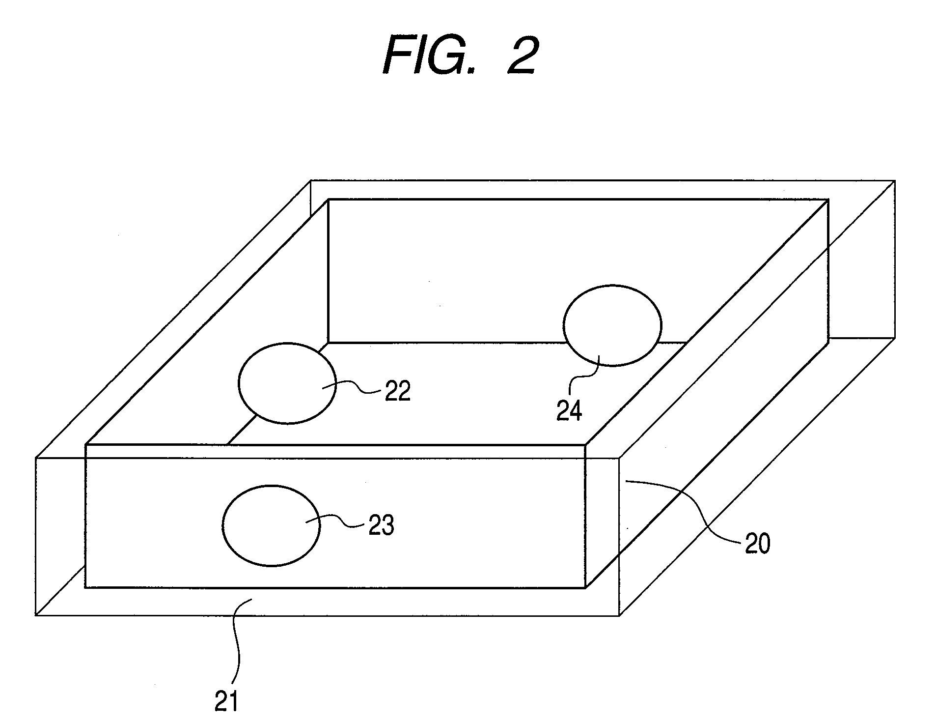
[0027]FIG. 2 is an overall view of the temperature ...
PUM
 Abstract
Description
Claims
Application Information