Polar Modulation Transmission Circuit and Communication Device

Inactive Publication Date: 2009-03-26
PANASONIC CORP
View PDF9 Cites 9 Cited by
  • Summary
  • Abstract
  • Description
  • Claims
  • Application Information

AI Technical Summary

Benefits of technology

[0026]As described above, a transmission circuit according to the present invention can increase the output power from the amplitude modulation section by amplifying the amplitude signal by the variable gain amplification section and attenuating the modulated signal by the variable attenuation section even when the value of the power information is small. Therefore, the transmission circuit can prevent the characteristic of the amplitude modulation section from deteriorating due

Problems solved by technology

Such a linear amplifier provides a superb linearity, but constantly consumes power accompanying a DC bias component and thus has a lower power efficiency than, for example, class C through class E nonlinear amplifiers.
Therefore, when applied to a mobile communication device using a battery as a power source, such a radio frequency power amplifier has a problem of being usable for only a short period of time due to the high power consumption thereof.
When applied to a base station device of a wireless system including a plurality of high power transmission circuits, such a radio frequenc

Method used


Image

  • Polar Modulation Transmission Circuit and Communication Device
  • Polar Modulation Transmission Circuit and Communication Device
  • Polar Modulation Transmission Circuit and Communication Device

Examples


first embodiment

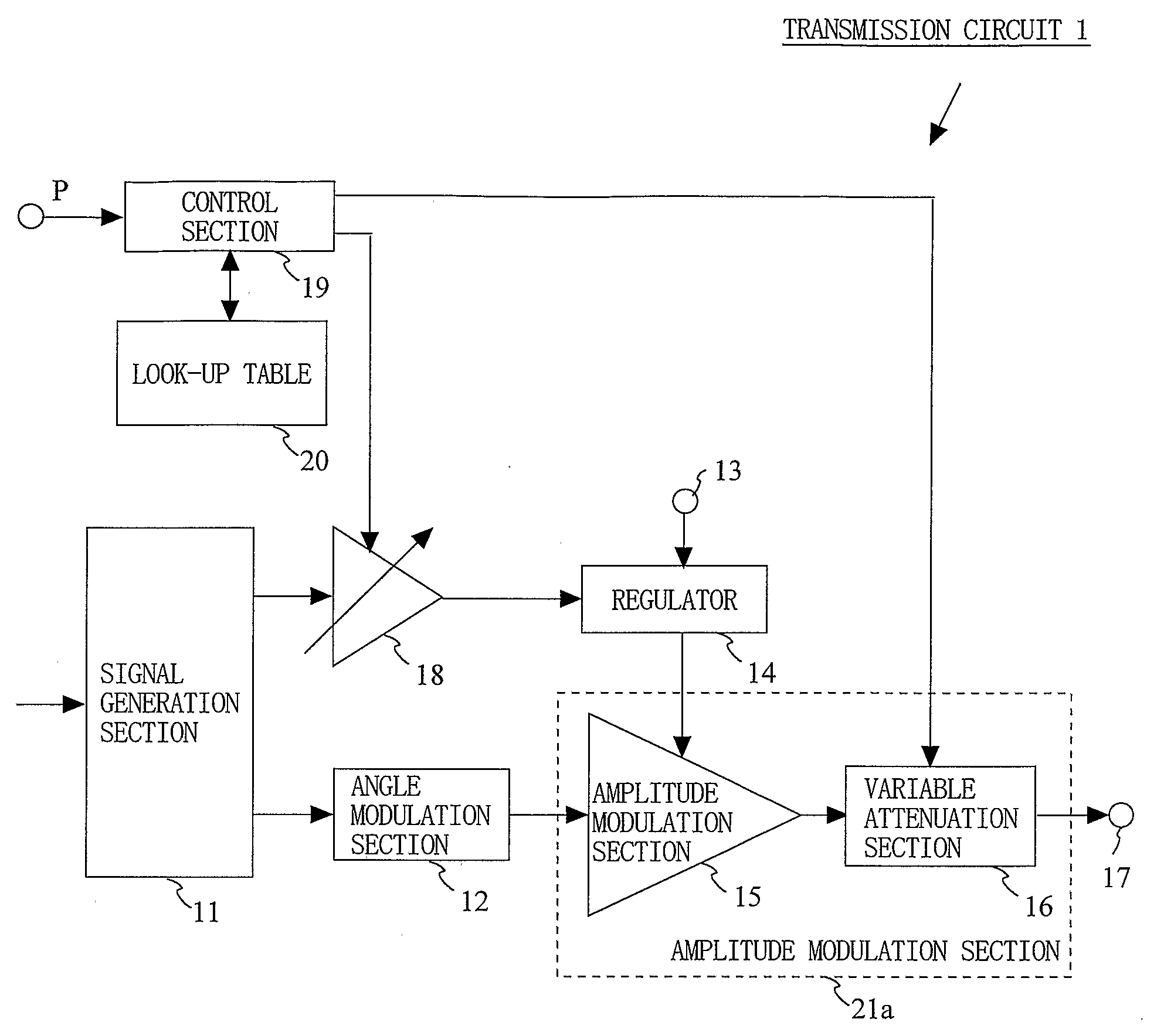
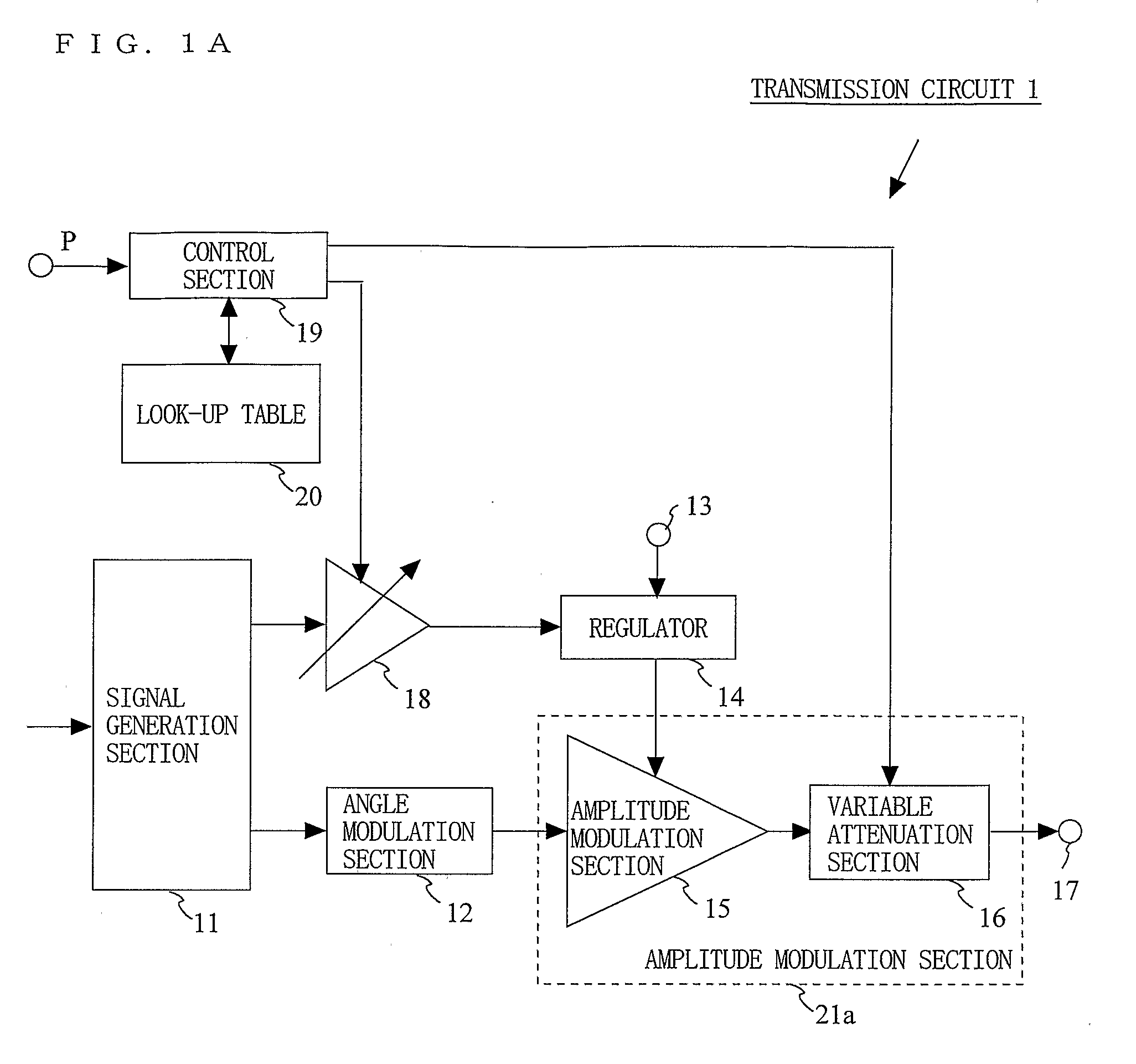
[0064]FIG. 1A is a block diagram showing an exemplary structure of a transmission circuit 1 according to a first embodiment of the present invention. As shown in FIG. 1A, the transmission circuit 1 includes a signal generation section 11, an angle modulation section 12, a power source terminal 13, a regulator 14, an amplitude modulation section 15, a variable attenuation section 16, an output terminal 17, a variable gain amplification section 18, a control section 19, and a look-up table 20.

[0065]The signal generation section 11 outputs an amplitude signal and a phase signal based on an amplitude component and a phase component obtained by performing signal processing on input data. The signal generation section 11 can include, for example, a polar coordinate signal generation section (not shown) for generating a polar coordinate signal. The polar coordinate signal generation section modulates input data and generates an amplitude signal and a phase signal, which are polar coordinat...

second embodiment

[0089]FIG. 9 is a block diagram showing an exemplary structure of a transmission circuit 2 according to a second embodiment of the present invention. As shown in FIG. 9, the transmission circuit 2 includes a signal generation section 11, an angle modulation section 12, a power source terminal 13, a regulator 14, an amplitude modulation section 15, a variable attenuation section 26, an output terminal 17, a variable gain amplification section 28, and a control section 29. In the transmission circuit 2 according to the second embodiment, the variable attenuation section 26, the variable gain amplification section 28 and the control section 29 operate in a different manner from those of the transmission circuit 1 according to the first embodiment.

[0090]In the transmission circuit 2, an assembly of the amplitude modulation section 15 and the variable attenuation section 26 may be labeled simply as an amplitude modulation section 21b, like in the transmission circuit 1.

[0091]FIG. 10 is a...

third embodiment

[0099]FIG. 12 is a block diagram showing an exemplary structure of a transmission circuit 3 according to a third embodiment of the present invention. Referring to FIG. 12, in the transmission circuit 3, a variable attenuation section 26b, a variable gain amplification section 28b, and a control section 29b operate in a different manner from those in the transmission circuit 2 according to the second embodiment. In the third embodiment, the variable attenuation section 26b can switch the attenuation by values greater than binary values. The variable gain amplification section 28b can switch the gain by values greater than binary values.

[0100]In the transmission circuit 3, an assembly of the amplitude modulation section 15 and the variable attenuation section 26b may be labeled simply as an amplitude modulation section 21c, like in the transmission circuit 1.

[0101]FIG. 13 is a block diagram showing an exemplary structure of the variable attenuation section 26b capable of switching the...


PUM


Abstract

A transmission circuit for outputting transmission signals with a low distortion and a high efficiency over a wide range of output power is provided. A signal generation section (11) generates an amplitude signal and a phase signal. An angle modulation section (12) performs angle modulation on the phase signal and outputs an angle-modulated signal. A regulator (14) receives the amplitude signal via a variable gain amplification section (18) and supplies a voltage controlled based on the magnitude of the amplitude signal to the amplitude modulation section (15). The amplitude modulation section (15) performs amplitude modulation on the angle-modulated signal and outputs a modulated signal to the variable attenuation section (16). When the value of power information is smaller than a predetermined threshold value, the control section (19) increases the gain of the variable gain amplification section (18) and the attenuation of the variable attenuation section (16).

Description

TECHNICAL FIELD[0001]The present invention relates to a transmission circuit usable for a communication device such as, for example, a mobile phone or a wireless LAN device, and more specifically to a transmission circuit for outputting transmission signals with a low distortion and a high efficiency over a wide range of output power and a communication device using the same.BACKGROUND ART[0002]Conventionally, a radio frequency power amplifier for amplifying a modulated signal with a variable envelope uses a class A or class AB linear amplifier for linearly amplifying the variable envelope. Such a linear amplifier provides a superb linearity, but constantly consumes power accompanying a DC bias component and thus has a lower power efficiency than, for example, class C through class E nonlinear amplifiers. Therefore, when applied to a mobile communication device using a battery as a power source, such a radio frequency power amplifier has a problem of being usable for only a short pe...

Claims


Application Information

Patent Timeline
IPC IPC(8): H03C5/00
CPCH04L27/368H04L27/361
Inventor MATSUURA, TORUADACHI, HISASHI
Owner PANASONIC CORP
Why Eureka
Try Eureka