Magnetoresistive element and magnetoresistive random access memory including the same

Inactive Publication Date: 2009-03-26
KK TOSHIBA
View PDF1 Cites 68 Cited by
  • Summary
  • Abstract
  • Description
  • Claims
  • Application Information

AI Technical Summary

Benefits of technology

[0011]The present invention has been made in view of these circumstances, and an object thereof is to provide a magnetoresistive element of a spin-transfer-torque writing type that requires only a low current to cause a magn

Problems solved by technology

As a result, it is difficult to use a low current and small-sized memory cells designed to have cap

Method used


Image

  • Magnetoresistive element and magnetoresistive random access memory including the same
  • Magnetoresistive element and magnetoresistive random access memory including the same
  • Magnetoresistive element and magnetoresistive random access memory including the same

Examples


first embodiment

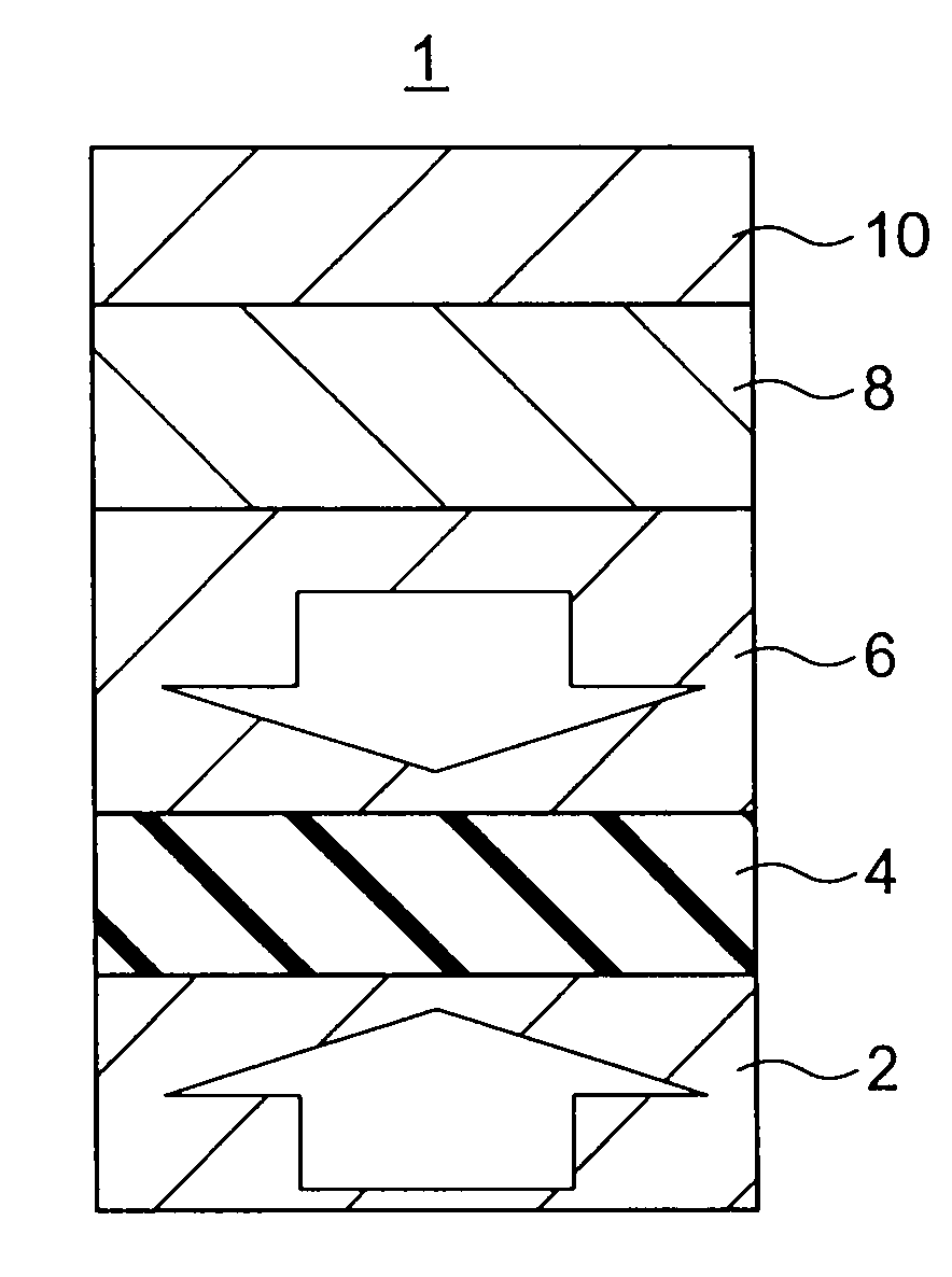
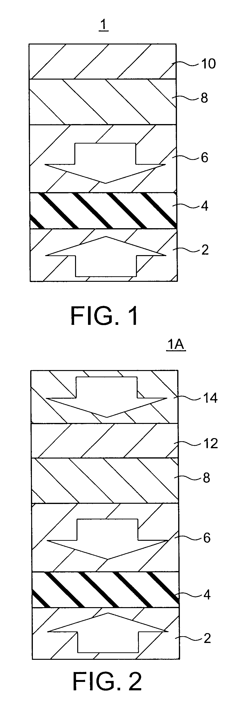
[0024]FIG. 1 shows a magnetoresistive element (MR element) in accordance with a first embodiment of the present invention. FIG. 1 illustrates the stacked structure as the principal body of the MR element of this embodiment. In FIG. 1, the arrows indicate magnetization directions.

[0025]The MR element is designed to be in one of two steady states in accordance with the direction of the bidirectional current flowing in a direction perpendicular to the film plane. The two steady states are associated with “0” date and “1” data, respectively, so that the MR element can store binary data. This is called the spin-transfer-torque writing method, by which the magnetization is varied with the direction of the current flowing direction and information corresponding to the magnetization state is stored.

[0026]The MR element 1 of this embodiment includes: a magnetization reference layer (hereinafter also referred to as a reference layer) 2 that is made of a ferromagnetic material or a ferrimagnet...

second embodiment

[0027]FIG. 2 shows a magnetoresistive element (MR element) in accordance with a second embodiment of the present invention. FIG. 2 illustrates the stacked structure as the principal body of the MR element of this embodiment. In FIG. 2, the arrows indicate magnetization directions.

[0028]The MR element 1A of the second embodiment includes: a magnetization reference layer 2 that is made of a ferromagnetic material or a ferrimagnetic material, has perpendicular magnetization, and has a magnetization of which a direction is invariable in one direction; a magnetization free layer 6 that is made of a ferromagnetic material or a ferrimagnetic material, has perpendicular magnetization, and has a magnetization of which a direction is variable; an intermediate layer 4 that is provided between the magnetization reference layer 2 and the magnetization free layer 6; a magnetic phase transition layer 8 that is formed in contact with the face of the magnetization free layer 6 on the opposite side f...

example 1

[0101]First, a specific example of a MR element of the first embodiment is described.

[0102]The MR element includes a stacked structure having a cap layer / an excitation layer 10 formed with MgO (0.7 nm) / a magnetic phase transition layer 8 formed with Fe50Rh50 (10 nm) / a magnetization free layer 6 formed with Fe50Pt50 (2 nm) and Fe (0.5 nm) / an intermediate layer (barrier layer) 4 made of MgO (1 nm) / a magnetization reference layer 2 formed with Co40Fe40B20 (2 nm) and Fe50Pt50 (10 nm) / a base layer.

[0103]The numeric values in the brackets indicate the layer thicknesses of the respective layers. Also, the magnetization reference layer 2 formed with Co40Fe40B20 (2 nm) and Fe50Pt50 (10 nm) has a magnetization of which a direction is invariable in one direction. The Co40Fe40B20 (2 nm) layer is an interfacial magnetic layer, and is inserted so as to increase the MR ratio. The Fe50Pt50 (10 nm) layer may have a magnetization of which a direction is invariable in one direction due to exchange cou...


PUM


Abstract

A magnetoresistive element includes: a first magnetization reference layer having magnetization perpendicular to a film plane, a direction of the magnetization being invariable in one direction; a magnetization free layer having magnetization perpendicular to the film plane, a direction of the magnetization being variable; a first intermediate layer provided between the first magnetization reference layer and the magnetization free layer; a magnetic phase transition layer provided on an opposite side of the magnetization free layer from the first intermediate layer, the magnetic phase transition layer being magnetically coupled to the magnetization free layer, and being capable of bidirectionally performing a magnetic phase transition between an antiferromagnetic material and a ferromagnetic material; and an excitation layer provided on an opposite side of the magnetic phase transition layer from the magnetization free layer, and causing the magnetic phase transition layer to perform the magnetic phase transition from the antiferromagnetic material to the ferromagnetic material.

Description

CROSS-REFERENCE TO RELATED APPLICATION[0001]This application is based upon and claims the benefit of priority from prior Japanese Patent Application No. 2007-248247 filed on Sep. 25, 2007 in Japan, the entire contents of which are incorporated herein by reference.BACKGROUND OF THE INVENTION[0002]1. Field of the Invention[0003]The present invention relates to a magnetoresistive element and a magnetoresistive random access memory including the magnetoresistive element.[0004]2. Related Art[0005]In recent years, a number of solid-state memories that record information have been suggested on the basis of novel principles. Among those solid-state memories, magnetoresistive random access memories (hereinafter also referred to as MRAMs) that take advantage of tunneling magneto resistance (hereinafter also referred to as TMR) have been known as solid-state magnetic memories. Each MRAM includes magnetoresistive elements (hereinafter also referred to as MR elements) that exhibit magnetoresisti...

Claims


Application Information

Patent Timeline
IPC IPC(8): G11B5/127
CPCB82Y25/00G01R33/093H01L43/10H01L27/228H01L43/08G11C11/16G11C11/1659G11C11/161G11C11/1675H10B61/22H10N50/85H10N50/10
Inventor YOSHIKAWA, MASATOSHIDAIBOU, TADAOMIKITAGAWA, EIJINAGASE, TOSHIHIKOKISHI, TATSUYAYODA, HIROAKI
Owner KK TOSHIBA
Why Eureka
Try Eureka