Voltage source converter and method of controlling a voltage source converter

a voltage source converter and voltage source technology, applied in the direction of power conversion systems, dc source parallel operation, conversion with reversal, etc., can solve the problems of insufficient blockage voltage requirements of semiconductor switching devices of the turn-off type (i, igbts), valves will experience either conduction losses or switching losses repetitively, and achieve the effect of reducing the requirements on individual components

Inactive Publication Date: 2009-03-26
ABB RES LTD
View PDF6 Cites 23 Cited by
  • Summary
  • Abstract
  • Description
  • Claims
  • Application Information

AI Technical Summary

Benefits of technology

[0006]An object of the present invention is to provide a voltage source converter (VSC) of th

Problems solved by technology

The blocking voltage requirement of semiconductor switching devices of the turn-off type (i.e., Insulated Gate Bipolar Transistors—IGBTS) is inadequate for the blocking volt

Method used


Image

  • Voltage source converter and method of controlling a voltage source converter
  • Voltage source converter and method of controlling a voltage source converter
  • Voltage source converter and method of controlling a voltage source converter

Examples


first embodiment

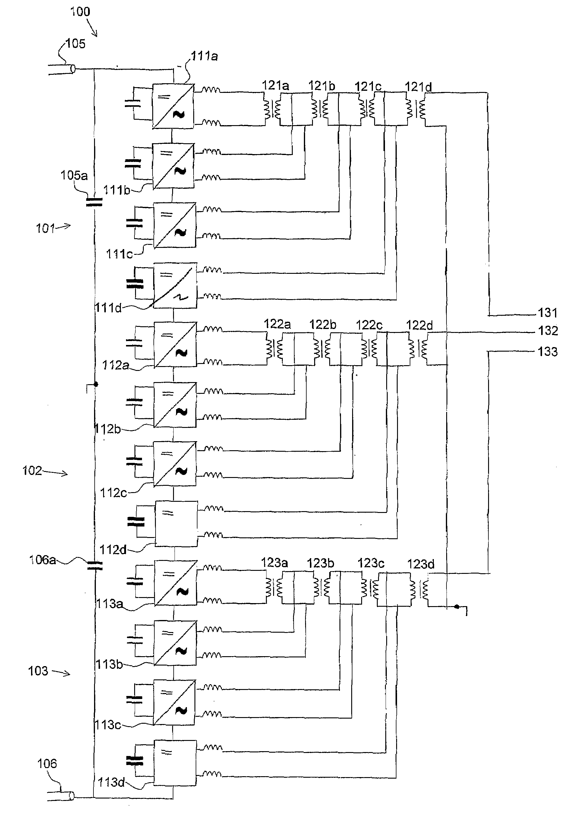
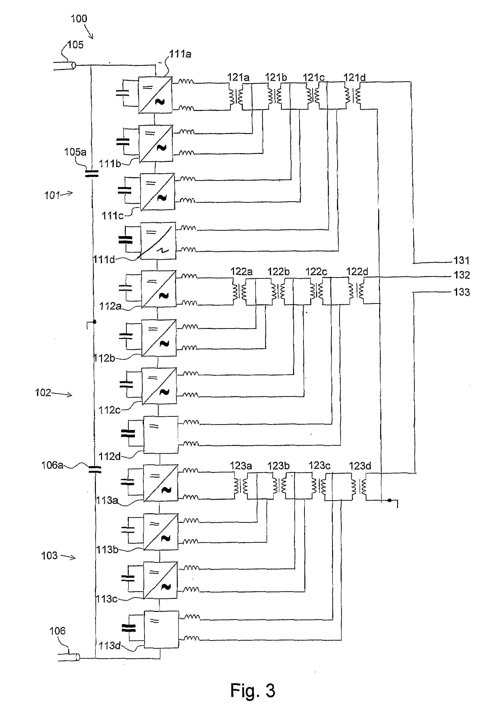
[0026]FIG. 3 shows an overall diagram of a VSC converter according to the invention. It is in some aspects similar to the prior art converter shown in FIG. 2. Thus, three phase legs 101, 102, 103 are connected in series between two pole conductors 105, 106 of a direct voltage network. More specifically, one end of the first phase leg 101 is connected to the positive pole conductor 105 and one end of the third phase leg 103 is connected to the negative pole conductor 106. The second phase leg 102 is interconnected between the first and third phase legs. Thus, the opposite ends of the series connection formed by an outer end of a respective outer phase leg of the series connection are connected to a respective pole conductor 105, 106.

[0027]Each phase leg 101-103 comprises four power conversion stages 111a-d-113a-d, respectively. These conversion stages can be conventional half- or full bridge power converters. Capacitors and inductors are connected to the conversion stages in order to...

fourth embodiment

[0040]In a fourth embodiment shown in FIG. 6, a VCS converter according to the invention is identical to the converter shown in FIG. 5 with the exception that it comprises conversion stages which are full bridge converters instead of half bridge converters.

[0041]In all the described embodiments, pulse width modulation (PWM) is applied. Three sinusoidal waveforms are compared with triangular carrier waveforms. The triangular carriers can be mutually phase shifted in order to achieve harmonic elimination.

[0042]In the upper portion of FIG. 6, sinusoidal and triangular voltages are shown. The resulting PWM voltage is plotted in the lower portion of the same figure.

[0043]FIG. 7 shows in the upper diagram a time graph of the converter voltage with a pulse width modulation. In the lower diagram phase currents are shown.

[0044]Preferred embodiments of a voltage source converter according to the invention have been described. A person skilled in the art realizes that these could be varied wit...


PUM


Abstract

A voltage source converter for conversion between dc and ac voltage includes at least two serially connected phase legs. The outputs of the conversion stages form phase outputs to be connected to a phase of an alternating voltage network via a respective transformer. The configuration of the conversion stages reduces the requirements on the individual components of the voltage source converter.

Description

FIELD OF INVENTION[0001]The present invention relates generally to a voltage source converter for converting direct voltage into alternating voltage and vice versa and more particularly to a VSC converter having improved performance as compared to prior art converters. The invention also relates to a method of controlling a voltage source converter.BACKGROUND[0002]A voltage source converter (VSC converter) is a device connected between a dc-voltage network and an ac voltage network and is subjected to forced commutation for transmitting electric power between the voltage-source dc-voltage and ac voltage networks connected thereto. One application of VSC converters is in High Voltage Direct Current (HVDC) applications, in which they offer a plurality of considerable advantages. Of these advantages can be mentioned that the consumption of active and reactive power may be controlled independently of each other and that there is no risk of commutating errors in the converter and hence n...

Claims


Application Information

Patent Timeline
IPC IPC(8): H02M7/68
CPCH02M7/537H02M2001/008H02M2001/0074H02M7/5395H02M1/0074H02M1/008
Inventor DIJKHUIZEN, FRANS
Owner ABB RES LTD
Why Eureka
Try Eureka