Temperature sensor for internal combustion engine

a technology of internal combustion engine and temperature sensor, which is applied in the field of temperature sensor, can solve the problems of high temperature temperature in the combustion chamber, high cost, and high cost of pressure sensor, and achieve the effect of efficient detection of misfire in the combustion chamber

Inactive Publication Date: 2009-03-26
DENSO CORP
View PDF13 Cites 25 Cited by
  • Summary
  • Abstract
  • Description
  • Claims
  • Application Information

AI Technical Summary

Benefits of technology

[0008]The present invention has been made in view of the above-mentioned problem, and an object of the present invention is t

Problems solved by technology

However, a following problem is involved in the pressure sensor disclosed in JP-A-2005-326336.
Temperature in the combustion chamber becomes very high when the mixture is fired and exploded, f

Method used


Image

  • Temperature sensor for internal combustion engine
  • Temperature sensor for internal combustion engine
  • Temperature sensor for internal combustion engine

Examples


first embodiment

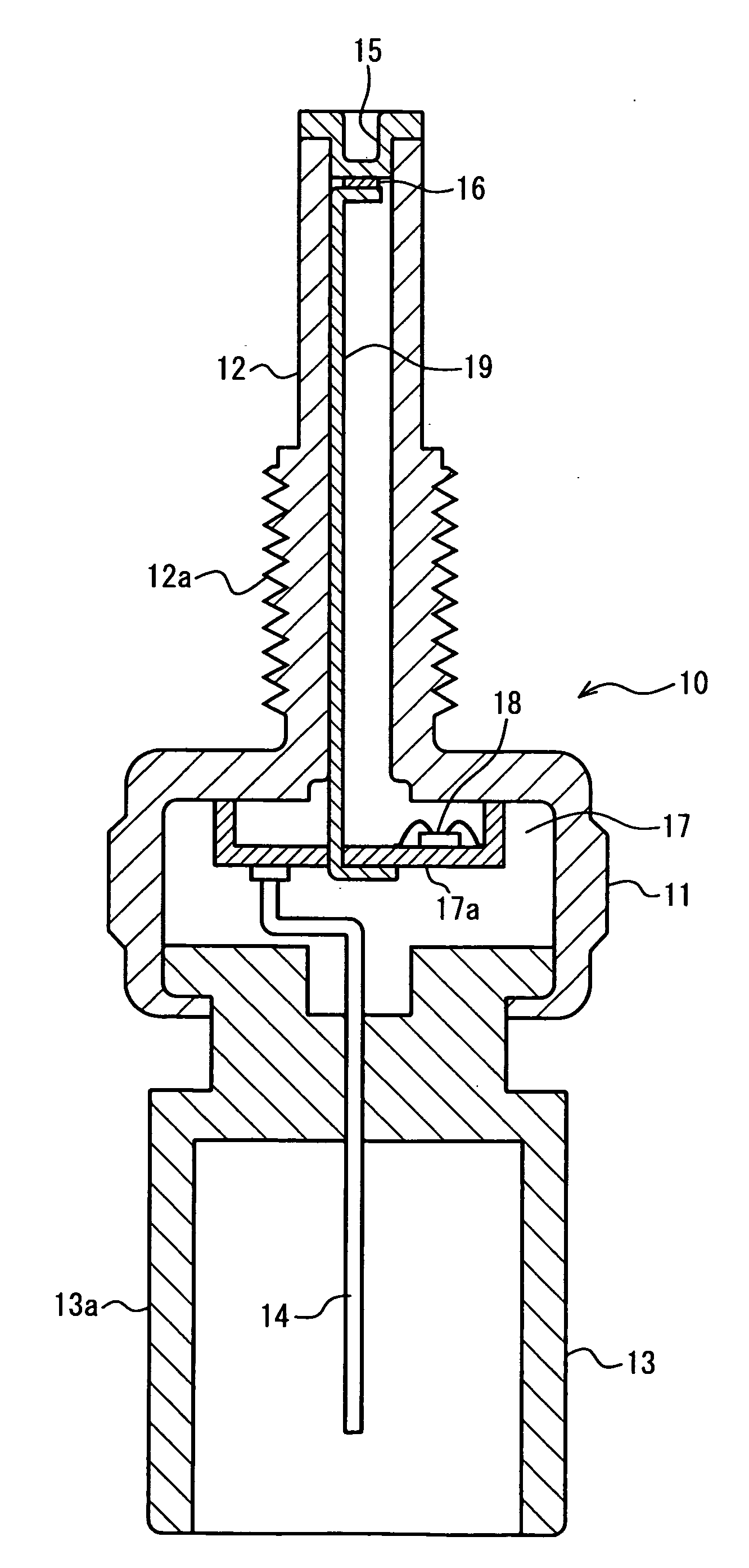
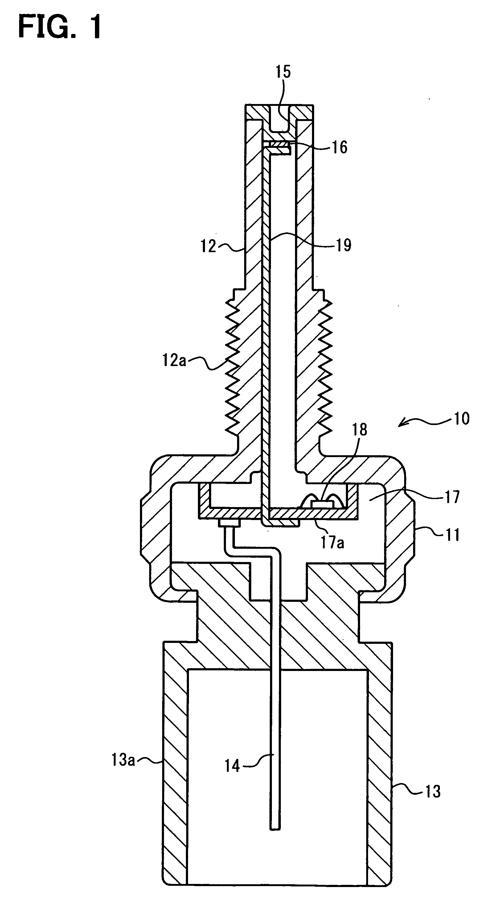
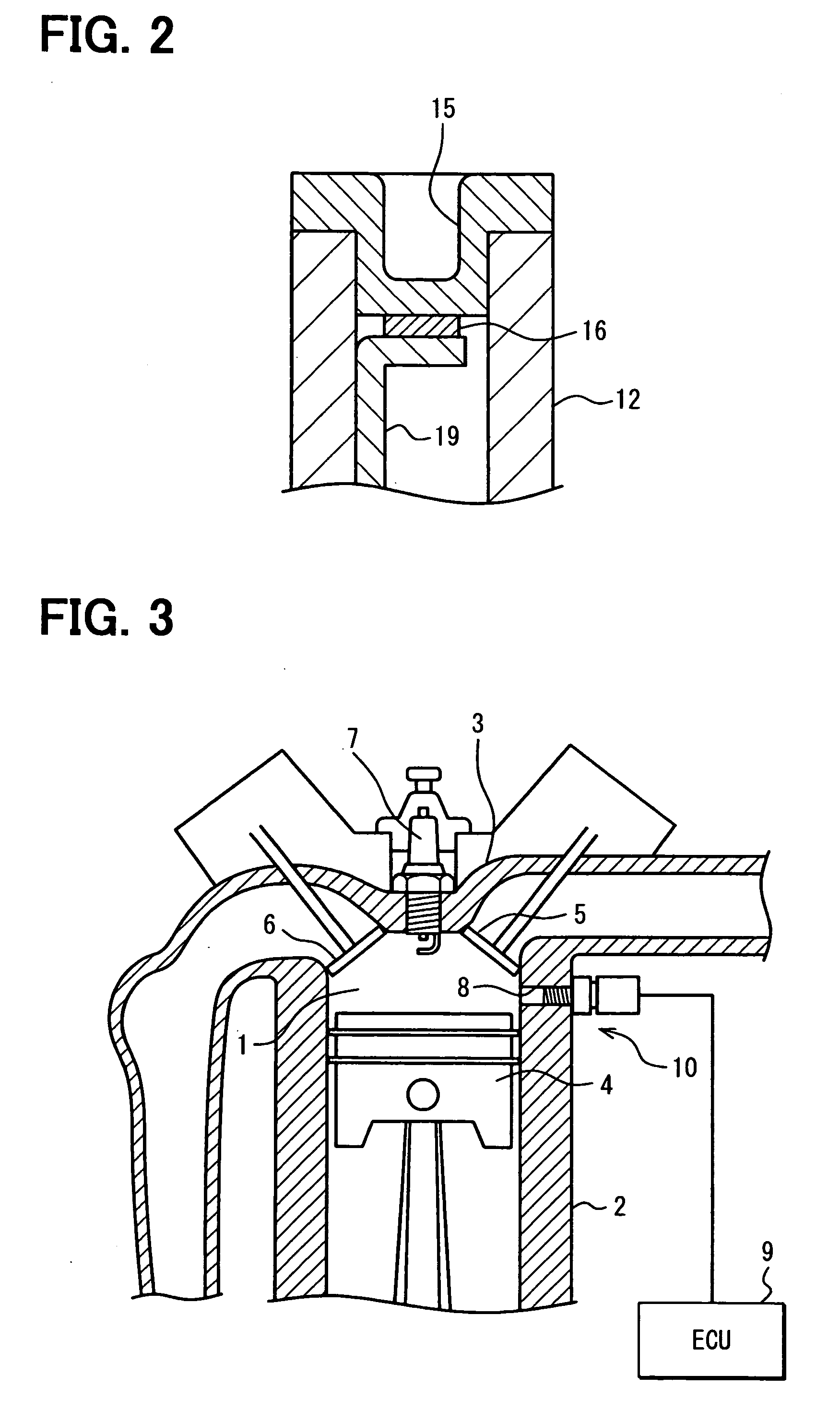
[0020]the present invention will be described with reference to FIGS. 1-3. First, referring to FIG. 3, a combustion chamber of an internal combustion engine, where a temperature sensor 10 of the present invention is installed, will be briefly explained. The combustion chamber 1 is formed by a cylinder block 2 and a cylinder head 3. A piston 4 is disposed in a cylinder and reciprocally moves back and forth in the cylinder. An intake valve 5 and an exhaust valve 6 are disposed at an upper portion of the combustion chamber 1. A spark plug 7 for igniting mixture gas introduced into the cylinder is also provided at an upper portion of the combustion chamber 1. A temperature sensor 10 according to the present invention is installed in a mounting hole 8 formed in the cylinder block 2. The temperature sensor 10 may be installed in the cylinder head 3. Signals from the temperature sensor 10 are fed to an electronic control unit (ECU) 9 for detecting a misfire in the combustion chamber 1.

[002...

fourth embodiment

[0032]the present invention is shown in FIG. 6. In this embodiment, the temperature sensor 31 is integrally formed with a spark plug. The spark plug includes a insulator 32 made of ceramics, a center electrode 33 held in the insulator, and a ground electrode 34 facing the center electrode 33, forming a spark gap therebetween. A screw 35 for connecting the spark plug to an engine is formed on a shell covering a tip of the insulator 32 (details are not shown). A probe portion 36 having an elongated inner space is provided in the insulator 32 in parallel to the center electrode 33. A sensor element 37 composed of an element such as a thin film thermistor is disposed at the tip of the probe portion 36, as shown in FIG. 6. The sensor element 37 is electrically connected to a processing circuit (not shown) contained in a connector housing (not shown) disposed at a bottom end of the insulator 32 through a conductor member 38. The conductor member 38 is hermetically sealed with a seal membe...


PUM


Abstract

A misfire in a combustion chamber of an internal combustion engine is detected by measuring a combustion chamber temperature with a temperature sensor element without using a pressure sensor having a low heat-resistive property. A temperature sensor includes an elongated probe portion extending from a housing. The housing is mounted on an engine so that the probe portion is exposed to the combustion chamber. A diaphragm is disposed on a tip of the probe portion, and a sensor element such as a thin film thermistor is mounted on the diaphragm, preferably on a rear surface of the diaphragm where the sensor element is not directly exposed to mixture gas in the combustion chamber. The sensor element may be embedded in the diaphragm. The probe portion of the temperature sensor may be integrally formed in a spark plug thereby to save a space for mounting the temperature sensor on the engine.

Description

CROSS-REFERENCE TO RELATED APPLICATION[0001]This application is based upon and claims benefit of priority of Japanese Patent Application No. 2007-243720 filed on Sep. 20, 2007, the content of which is incorporated herein by reference.BACKGROUND OF THE INVENTION[0002]1. Field of the Invention[0003]The present invention relates to a temperature sensor for detecting temperature in a combustion chamber of an internal combustion engine.[0004]2. Description of Related Art[0005]In a system for controlling operation of an internal combustion engine, an electronic control unit (ECU) controls engine operation to optimum conditions based on signals fed from various sensors. A misfire in a combustion chamber is detected, as one of such signals, by a pressure sensor for detecting pressure in the combustion chamber. An example of the misfire detection based on the pressure in the combustion chamber is disclosed in JP-A-2005-326336.[0006]The pressure sensor disclosed therein is composed of a housi...

Claims


Application Information

Patent Timeline
IPC IPC(8): G01K1/14
CPCG01K1/14G01M15/11G01K2205/00
Inventor TAKEUCHI, HISAYUKI
Owner DENSO CORP
Why Eureka
Try Eureka