Rolling bearing device and turbocharger incorporating same

a technology of rolling bearings and turbochargers, which is applied in the direction of machines/engines, mechanical equipment, liquid fuel engines, etc., can solve the problems of reducing durability, affecting the performance of the engine, so as to reduce the adverse effects of heat from the turbine wheel and reduce the effect of vibration of the turbine sha

Inactive Publication Date: 2009-03-26
JTEKT CORP
View PDF18 Cites 48 Cited by
  • Summary
  • Abstract
  • Description
  • Claims
  • Application Information

AI Technical Summary

Benefits of technology

[0024]In the present invention, even when the rolling bearings are located in sufficiently spaced relation, for example, to the turbine wheel in the ...

Problems solved by technology

Therefore, that rolling bearing (the turbine wheel-side one of the pair of rolling bearings) which is disposed close to the turbine wheel is particularly affected by heat, and problems such as seizure and lowered durability are liable to arise.
However, a larger amount of engine oil must be supplied to the turbine wheel-side rolling bearing in order to sufficiently cool it, and a driving power of an engine oil pump need to be increased, and therefore an energy loss of the engine becomes large.
However, when the rolling beari...

Method used


Image

  • Rolling bearing device and turbocharger incorporating same
  • Rolling bearing device and turbocharger incorporating same
  • Rolling bearing device and turbocharger incorporating same

Examples


Embodiment Construction

[0032]A preferred embodiment of the present invention will now be described with reference to the drawings.

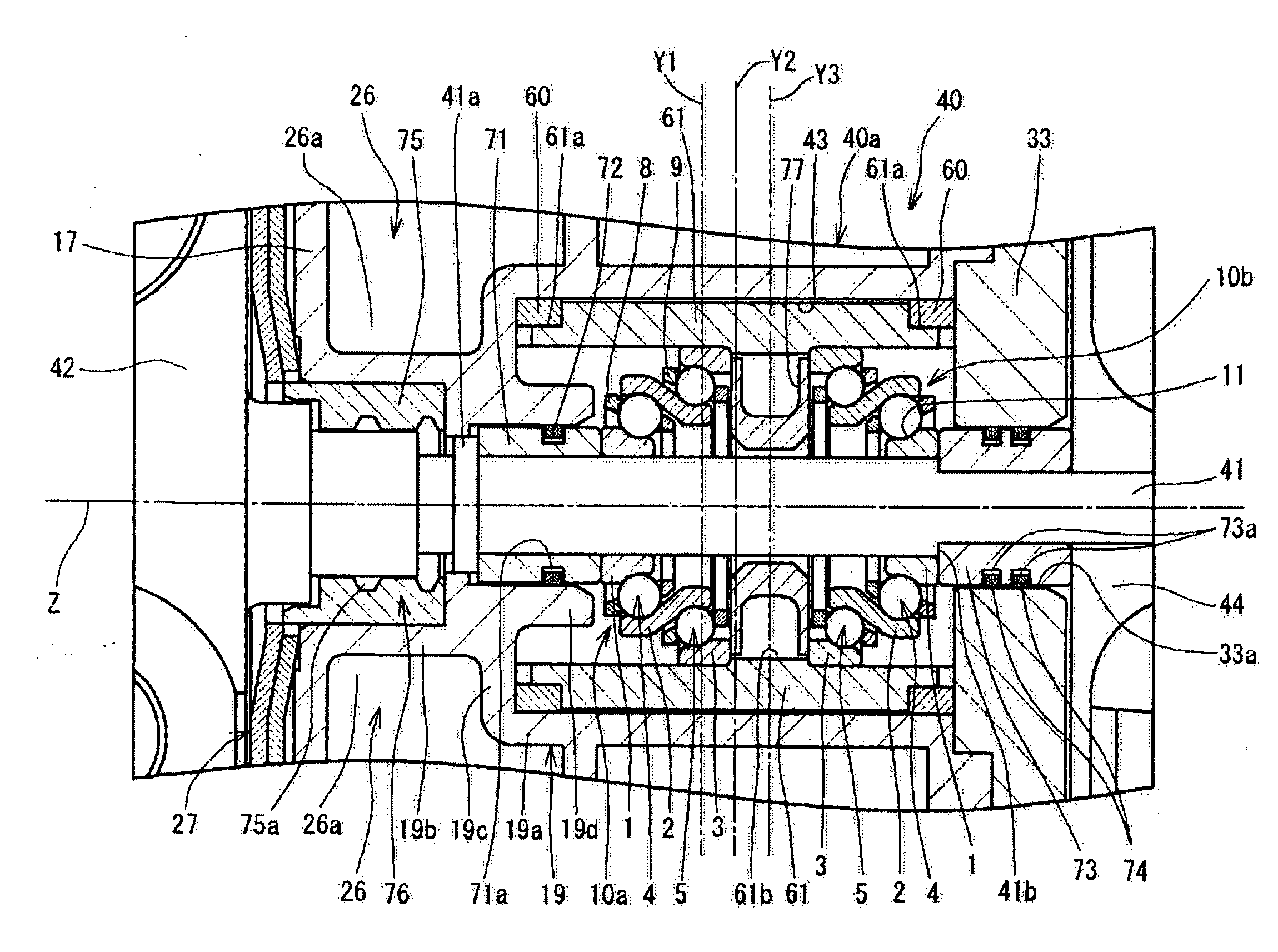
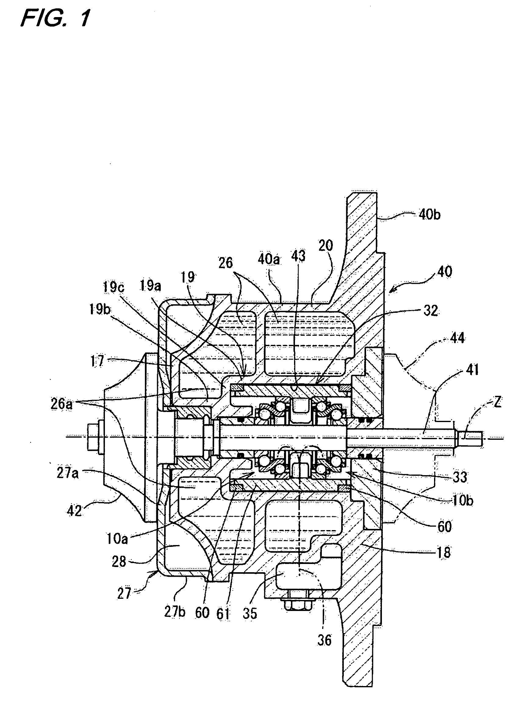
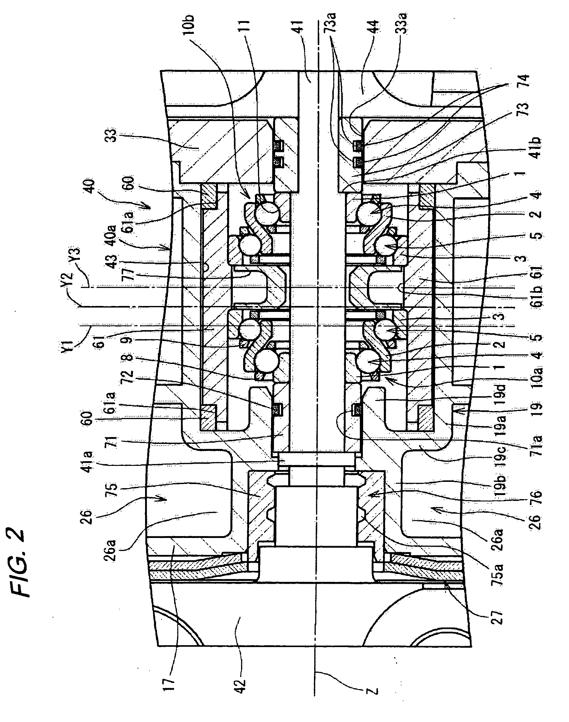
[0033]FIG. 1 is a cross-sectional view of a turbocharger employing one preferred embodiment of a rolling bearing device of the invention. This turbocharger comprises a casing 40, and a turbine shaft 41, and this turbine shaft 41 is rotatably supported in the casing 40 through the rolling bearing device 32. The turbocharger is used, for example, as a turbocharger for an engine of an automobile.

[0034]A turbine wheel 42 is fixed to one end portion of the turbine shaft 41, while a compressor wheel 44 is fixed to the other end portion of the turbine shaft 41. The turbine wheel 42 is disposed in a passageway for flowing exhaust gas (exhausted from the engine) therethrough, and the compressor wheel 44 is disposed in a passageway for supplying compressed air to the engine.

[0035]The casing 40 includes a body portion 40a having a cylindrical outer periphery, and a flange portion 40b exte...


PUM


Abstract

A rolling bearing device includes a bearing housing supported on a casing of a turbocharger, and a pair of rolling bearings mounted within the bearing housing and rotatably supporting a turbine shaft. A middle position between the pair of rolling bearings in an axial direction and a central portion of the bearing housing in the axial direction are offset from each other in the axial direction. Each of the rolling bearings includes an inner ring, an outer ring, an intermediate ring interposed between the inner and outer rings, a row of rolling elements rollably interposed between the inner ring and the intermediate ring, and a row of rolling elements rollably interposed between the intermediate ring and the outer ring. The intermediate ring has a damper function to be very slightly displaced or very slightly deformed elastically so as to damp vibration produced during rotation of the turbine shaft.

Description

BACKGROUND OF THE INVENTION[0001]1. Field of the Invention[0002]This invention relates to a rolling bearing device and a turbocharger incorporating the same.[0003]2. Related Art[0004]Turbochargers have been extensively used in automobiles in order to enhance an engine performance. JP-A-2002-98158 discloses a turbocharger comprising a casing, a turbine shaft rotatably supported within the casing through a pair of rolling bearings, a turbine wheel fixed to one end of the turbine shaft, and a compressor wheel fixed to the other end of the turbine shaft. The pair of rolling bearings are spaced from each other in an axial direction, and are mounted on an inner peripheral surface of a bearing housing of a tubular shape. The bearing housing is supported in a central hole formed in the casing.[0005]In the turbocharger of JP-A-2002-98158, in order to reduce vibration due to high-speed rotation of the turbine shaft, engine oil is supplied to an area between the outer peripheral surface of the...

Claims


Application Information

Patent Timeline
IPC IPC(8): F04D29/049F16C19/08
CPCF16C19/55F16C33/588F16C2360/24F16C19/163F16C19/548
Inventor UENO, HIROSHISHIRAKI, TOSHIHIKOOSHIMA, AKIONAKASHITA, TOMONORIOHTSUKI, MASAAKIBANDO, SHIGENORIABE, MASAKINAKATA, RYUJIKIDA, TAKEHISA
Owner JTEKT CORP
Why Eureka
Try Eureka