Device and method for condensing, drying and heating flue gas

A flue gas condensation and heating device technology, which is applied to chemical instruments and methods, steam condensation, separation methods, etc., can solve the problems of flue gas temperature reduction, etc., to increase the discharge temperature, prevent corrosion and scaling, and achieve high heat transfer efficiency Effect

Inactive Publication Date: 2011-05-18
SOUTHEAST UNIV
View PDF9 Cites 7 Cited by
  • Summary
  • Abstract
  • Description
  • Claims
  • Application Information

AI Technical Summary

Problems solved by technology

[0003] The conventional method of recovering flue gas condensate is to reduce the temperature of the flue gas to below the dew point of water vapor by means of cooling and heat exchange, and the water vapor in the flue gas will condense into water and be discharged, but this will cause a significant drop in the temperature of the flue gas

Method used


Image

  • Device and method for condensing, drying and heating flue gas
  • Device and method for condensing, drying and heating flue gas

Examples


Embodiment Construction

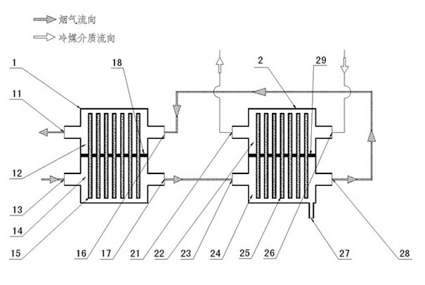
[0017] In the flue gas condensation and drying heating device of the present invention, the high-temperature heat pipe heat exchanger 1 includes a high-temperature heat pipe heat exchanger cold fluid outlet 11, a high-temperature heat pipe heat exchanger condensation section 12, a high-temperature heat pipe heat exchanger hot fluid inlet 13, and a high-temperature heat pipe Heat exchanger evaporation section 14, high temperature heat pipe 15, high temperature heat pipe heat exchanger cold fluid inlet 16, high temperature heat pipe heat exchanger hot fluid outlet 17, high temperature heat pipe 15 located in high temperature heat pipe heat exchanger 1 is separated by first isolation layer 18 It is divided into two parts: the condensing section 12 of the upper high-temperature heat pipe heat exchanger and the evaporating section 14 of the lower high-temperature heat pipe heat exchanger. The cold fluid outlet 11 of the heat pipe heat exchanger, the two ends of the evaporation secti...


PUM


Abstract

The invention discloses a device and method for condensing, drying and heating flue gas, in particular to a device and method for recovering and recycling condensed water in the flue gas and meeting the temperature requirement for diffusing pollutants in the flue gas to the upper air. A heat fluid outlet of a high-temperature heat tube heat exchanger of the device is connected with a heat fluid inlet of a low-temperature heat tube heat exchanger; a heat fluid outlet of the low-temperature heat tube heat exchanger is connected with a cold fluid inlet of the high-temperature heat tube heat exchanger. The method comprises the following steps of: introducing wet flue gas into an evaporation section of the high-temperature heat tube heat exchanger; heating a high-temperature heat tube; feedingthe wet flue gas subjected to temperature drop into an evaporation section of the low-temperature heat tube heat exchanger; feeding a coolant medium into the evaporation section of the low-temperature heat tube heat exchanger; reducing the temperature of the wet flue gas to below a dew point of water vapor under the action of the low-temperature heat tube; condensing the water vapor in the wet flue gas into water and discharging the water from a flue gas condensed water outlet; discharging the coolant medium absorbing the heat from a cold fluid outlet of the low-temperature heat tube heat exchanger; and heating the condensed dried flue gas by a high-temperature heat tube and discharging the heated flue gas by a chimney.

Description

technical field [0001] The invention relates to a device and method for recovering boiler flue gas condensed water, in particular to a flue gas condensation drying heating device and method. Background technique [0002] With the development of social economy and the improvement of people's living standards, water resources are increasingly precious. The flue gas produced by the combustion of fuels (including coal, oil, natural gas, biomass and municipal solid waste) contains a large amount of water vapor, which is discharged into the atmosphere through the chimney, which not only causes a great waste of water resources, but also causes water vapor in the chimney Condensation in the middle will condense into water and flow down the wall, causing corrosion and scaling of the chimney. If the water vapor in the flue gas can be recycled and utilized, improving the utilization rate of reclaimed water is of great significance to areas where water resources are scarce. [0003] T...

Claims


Application Information

Patent Timeline
Patent Type & Authority Applications(China)
IPC IPC(8): B01D5/00B01D53/26F28D15/02
Inventor 沈来宏张海峰
Owner SOUTHEAST UNIV
Why Eureka
Try Eureka