
System and method for measurement of biological parameters of a subject

a biological parameter and system technology, applied in the field of optical measurement techniques, can solve the problems of reducing the quality of measured signals, inability to measure accurately, and inability to accurately detect the movement of objects,

Inactive Publication Date: 2009-03-26
ELFI TECH
View PDF6 Cites 51 Cited by
  • Summary
  • Abstract
  • Description
  • Claims
  • Application Information

AI Technical Summary

Benefits of technology

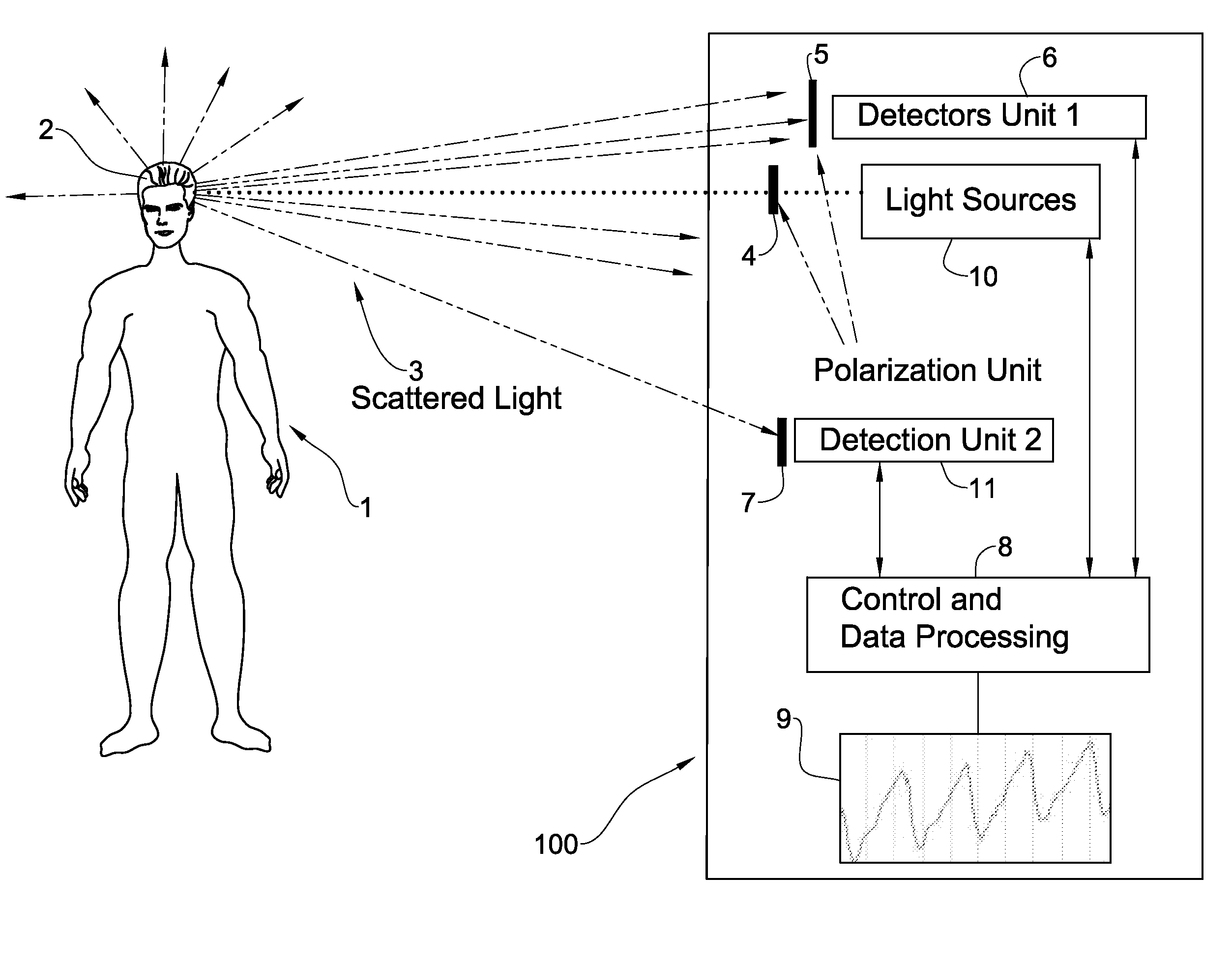
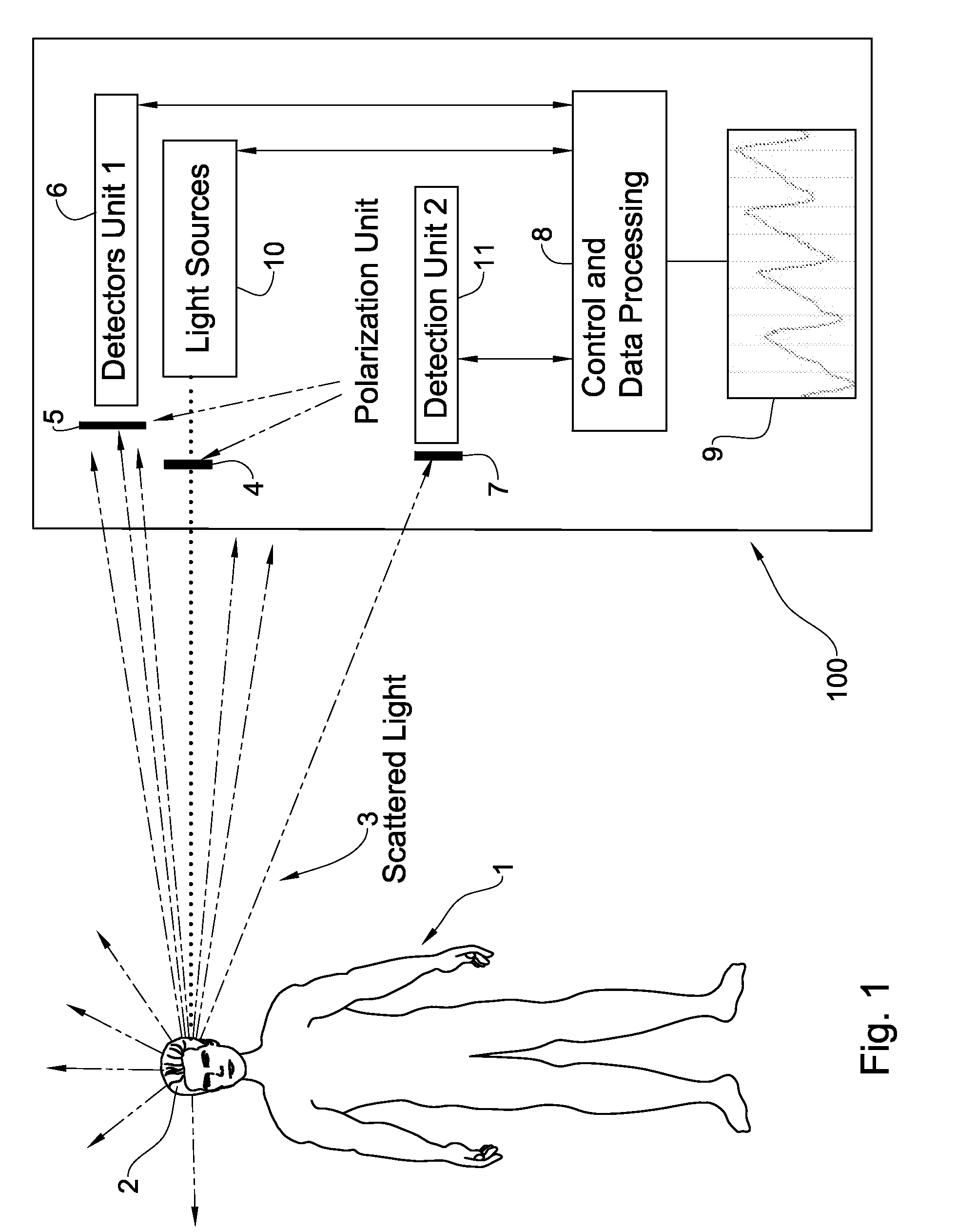
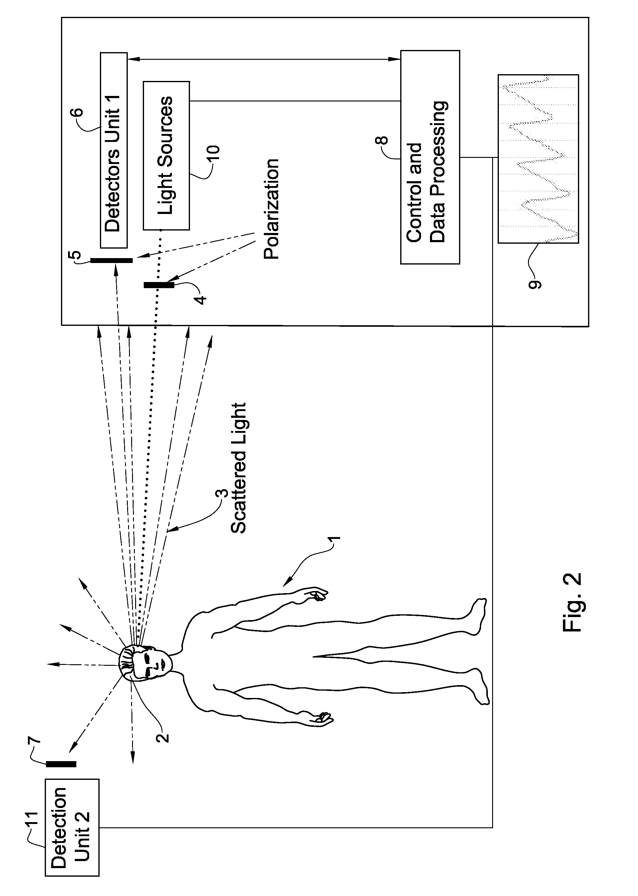
[0008]There is a need in the art to provide a system for use in monitoring of biological parameters of a subject. The system includes (i) an illumination unit including at least one light source of at least one pre-selected wavelength band, to be applied to a selected region in the subject; and (ii) a detection system configured for measuring reflections of said light at different angles and different spatial locations with respect to the illuminated region. The detection unit is configured and operable to detect spatially separated light components corresponding to the specular dependent component of the signal and the pulsatile-related diffused component of the signal coming from the subject in different directions respectively, thereby defining at least two independent channels of information, enabling identification of the reflected signal part dependent on motion effects. The system includes a control unit connectable to said illumination unit and to said detection system, said control unit being configured to analyze at least two independent channels of information indicative of the detected signals, to eliminate the signal part dependent on motion effects and determine one or more biological parameters such as heart rate.
[0022]There is another broad aspect of the present invention to provide a method for use in non-invasive determination of biological parameters of a subject. The method includes illuminating a selected region of the subject by light of at least one wavelength, and detecting reflections of said light from at least two distant geometrical locations in said selected region, such as to detect spatially separated light components coming from the illuminated region in different directions respectively, thereby defining at least two independent channels of information, enabling identification of the reflected signal part dependent on motion effects.
[0031]During prolonged monitoring of a sleep status under home or even laboratory environment, any contact between the sensor and subject has to be minimized. In this case, a distant monitoring will be helpful to secure a good sleep quality, on the one hand, and to provide a continuous monitoring of heart rate, oxygen saturation and other parameters essential as diagnostic and follow-up tools.
[0035]Thus, the present invention provides for deriving the CNS characteristics from blood measurement. The latter is obtained for a subject as a base line and the CNS characteristics are measured for the subject while exposed to pre-defined visual or audio information, which is chosen to be verified and revealed and then compared to the CNS reactions prior provocation stimulus and after it is performed to reveal if said subject is aware of this pre-selected information. For example, an unrevealed, distant monitoring of HRV (heart rate variability) of a subject is carried out for a few minutes, in order to create a base line of HRV. At the next stage, the examined subject is exposed, without any previous notice, to a pre-prepared audio message, containing some kind of information, which may be recognized by the examined subject only if he is aware of this information. In case that the information (name of a certain person, for example) is recognized by this subject, the CNS sympathetic system will cause an immediate change of the HRV pattern, which will be detected by a surveillance system. This will help to find out whether an examined subject is aware of information which he is not supposed to be aware of. In this test, the different interference factors of standard “lie detector” tests where the subject is prepared to the test are overcome. It should be noted that the reaction of aware tested subject can lead to cognitive irregular CNS reaction, which can lead to misinterpretation of the test results. This problem is avoided by doing a distant test.

Problems solved by technology

Motion artifact corruption of near infrared plethysmography, causing both measurement inaccuracies and false alarm conditions, is a primary restriction in the current clinical practice and future applications of this useful technique.
The most disturbing motion artifact results from a frequently occurring unpredictable relative mechanical movement between an optical sensor and the subject.
In the case where the optical and mechanical coupling between the sensor and body surface is weak, a very strong motion artifact may drastically reduce the quality of the measured signal.
It is clear that motion artifact is an inherent problem for any distant or non-contact measurement of optical signals from the body.
Due to the lack of coupling, even very subtle movement of an examined subject can result in very significant signal corruption.
In terms of a Fourier-spectral analysis, a sharp signal form, being originated by motion artifact, would contribute over all the frequency ranges, and it is therefore very difficult to extract a biological signal by utilizing any frequency specific features, like as it is done for pulsatile signal, for example.

Method used


Image

  • System and method for measurement of biological parameters of a subject
  • System and method for measurement of biological parameters of a subject
  • System and method for measurement of biological parameters of a subject

Examples


Embodiment Construction

[0049]The configuration and operation of the measurement system and the method of monitoring used therein can be better understood with reference to the drawings, wherein like reference numerals denote like elements through the several views and the accompanying description of non-limiting, exemplary embodiments.

[0050]Reference is made to FIGS. 1 to 3 being schematic diagrams of different configurations of distant measurement systems. To facilitate understanding, the same reference numbers are used for identifying components that are common in all the examples.

[0051]All of these configurations include an illumination unit including at least one light source unit 10, and a detection system, which in the present examples includes two detection units 6 and 11. Light source unit 10 may include a multi-LED element, or a laser-diodes' array, or tunable laser, or a white light source with band-pass filters with shutters, or any combination of these light sources, enabling to illuminate a s...


PUM


Abstract

Disclosed is a system and method for use in monitoring of biological parameters of a subject. The system includes an illumination unit including at least one light source of at least one pre-selected wavelength band, to be applied to a selected region in the subject; and a detection system configured for measuring reflections of the light at different angles and different spatial locations with respect to the illuminated region. The detection system is configured and operable to detect spatially separated light components corresponding to the specular dependent component of the signal and the pulsatile-related diffused component of the signal coming from the subject in different directions respectively, thereby defining at least two independent channels of information, enabling identification of the reflected signal part dependent on motion effects.

Description

RELATED APPLICATIONS[0001]This application is a Continuation of PCT application serial number PCT / IL2007 / 000710, filed on Jun. 13, 2007, which in turn claims the benefit under 35 USC 119(e) of U.S. Provisional Application No. 60 / 812,973, filed on Jun. 13, 2006, both of which are incorporated herein by reference in their entirety.FIELD OF THE INVENTION[0002]The present invention is generally in the field of optical measurement techniques on a subject used in medical and other applications, and relates to a system and method capable of distant or non-contact monitoring of the biological parameters of a subject.BACKGROUND OF THE INVENTION[0003]A photoplethysmograph, i.e. an optical volumetric measurement of an organ, is often obtained by using a pulse oximeter which illuminates the skin and measures changes in light absorption. A conventional pulse oximeter monitors the perfusion of blood to the dermis and subcutaneous tissue of the skin. The change in volume is detected by illuminatin...

Claims


Application Information

Patent Timeline
IPC IPC(8): A61B5/00
CPCA61B5/0059A61B5/7214A61B5/4818A61B5/4806
Inventor FINE, ILYA
Owner ELFI TECH
Learn More