MRI breast image magnet structure

a magnet structure and breast image technology, applied in the field of medical imaging, can solve the problems of limiting some imaging applications, and inadequate scanning field strength, and achieve the effect of reducing the reflection

Inactive Publication Date: 2009-03-26
ISRAEL HENRY M
View PDF3 Cites 24 Cited by
  • Summary
  • Abstract
  • Description
  • Claims
  • Application Information

AI Technical Summary

Benefits of technology

[0010]In accordance with non-limiting embodiments of the present invention, the apparatus includes a magnet assembly for producing a static magnetic field in a shaped steel “C” core, a gradient field generating assembly for generating magnetic field gradients in at least two orthogonal planes for producing MR images and a radiofrequency (RF) coil assembly for transmitting a broad band radiofrequency pulse and a RF field matching structure to simulate an infinite volume to the RF coils. The RF coils detect a plurality of magnetic resonance (MR) signals induced from the subject in response to the RF pulse and the matching structure reduces the effect of reflections from the magnetic structure. The apparatus further includes a device for supporting the subject with respect to the magnet assembly and a plurality of digital receivers for receiving the plurality of MR signals. The receivers are adapted to be adjusted in phase and frequency to produce parallel spectral levels as inputs to three-dimensional K-space. A digital processor is further incorporated to transform the K-space date to an image.
[0011]Further, the open magnetic structure and speed of processing and producing an image allow real time, manual control of treatment and biopsies. The patient support allows static breast imaging using a horizontal table with breast locating receptacles. Further variations in the support structure allow imaging of extremities such as arms and legs with detail, weight bearing, and studying the finger, wrist, elbow, knee and ankle joints.

Problems solved by technology

Conventional extremity scanners, however, have a major drawback in that, due to design constraints, sufficient scanning field strength is not provided to adequately image the target body part.
Typically, the usable field within the gap is provided at a strength of no greater than 0.2 Tesla, which may limit some imaging applications.
At least one design provides a larger field strength, but the structural design is such that weight-bearing scans are not possible, so the applications for this design are limited.
Most patients are uncomfortable and become fidgety when confined in this manner, making it hard to obtain meaningful diagnostic information.
In addition, direct hand delivered treatment or biopsy under MRI control is impossible in the present system configurations.

Method used


Image

  • MRI breast image magnet structure
  • MRI breast image magnet structure
  • MRI breast image magnet structure

Examples


Embodiment Construction

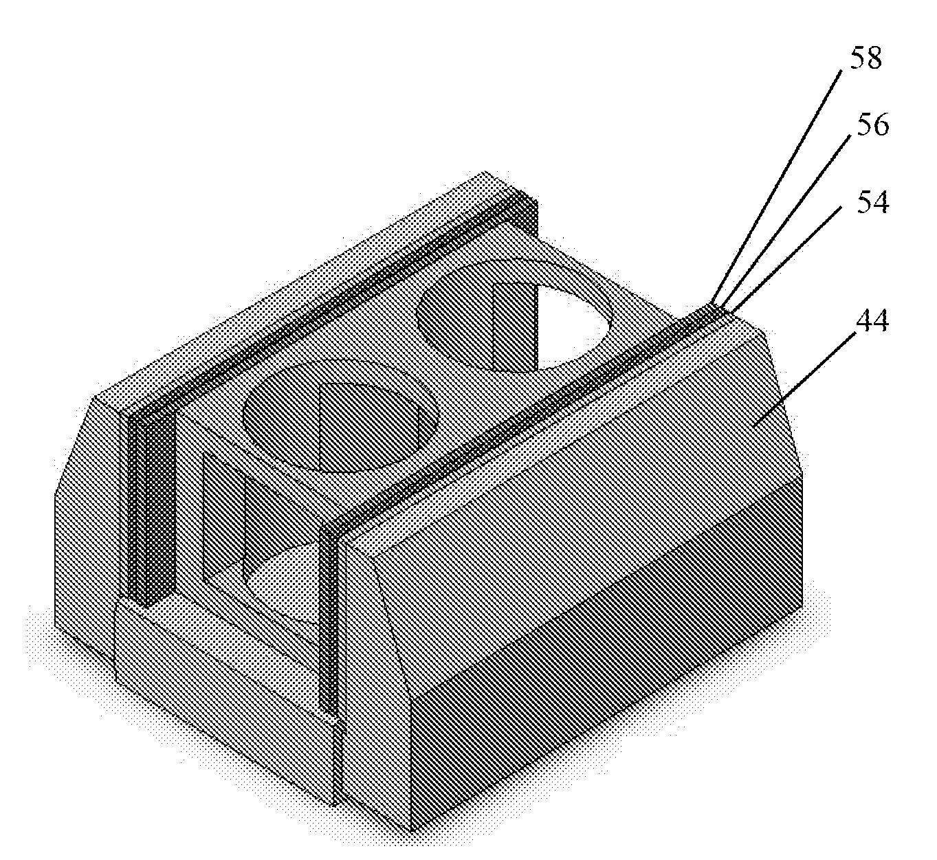
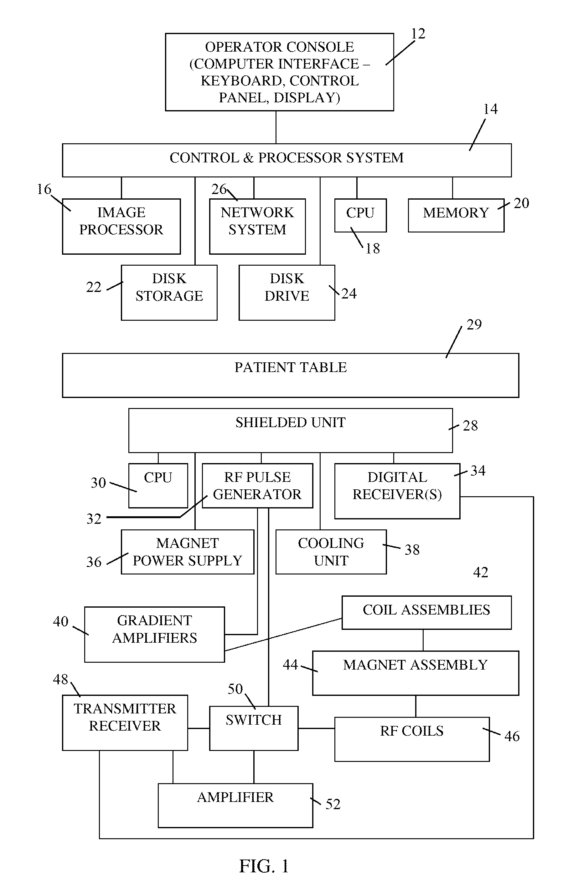
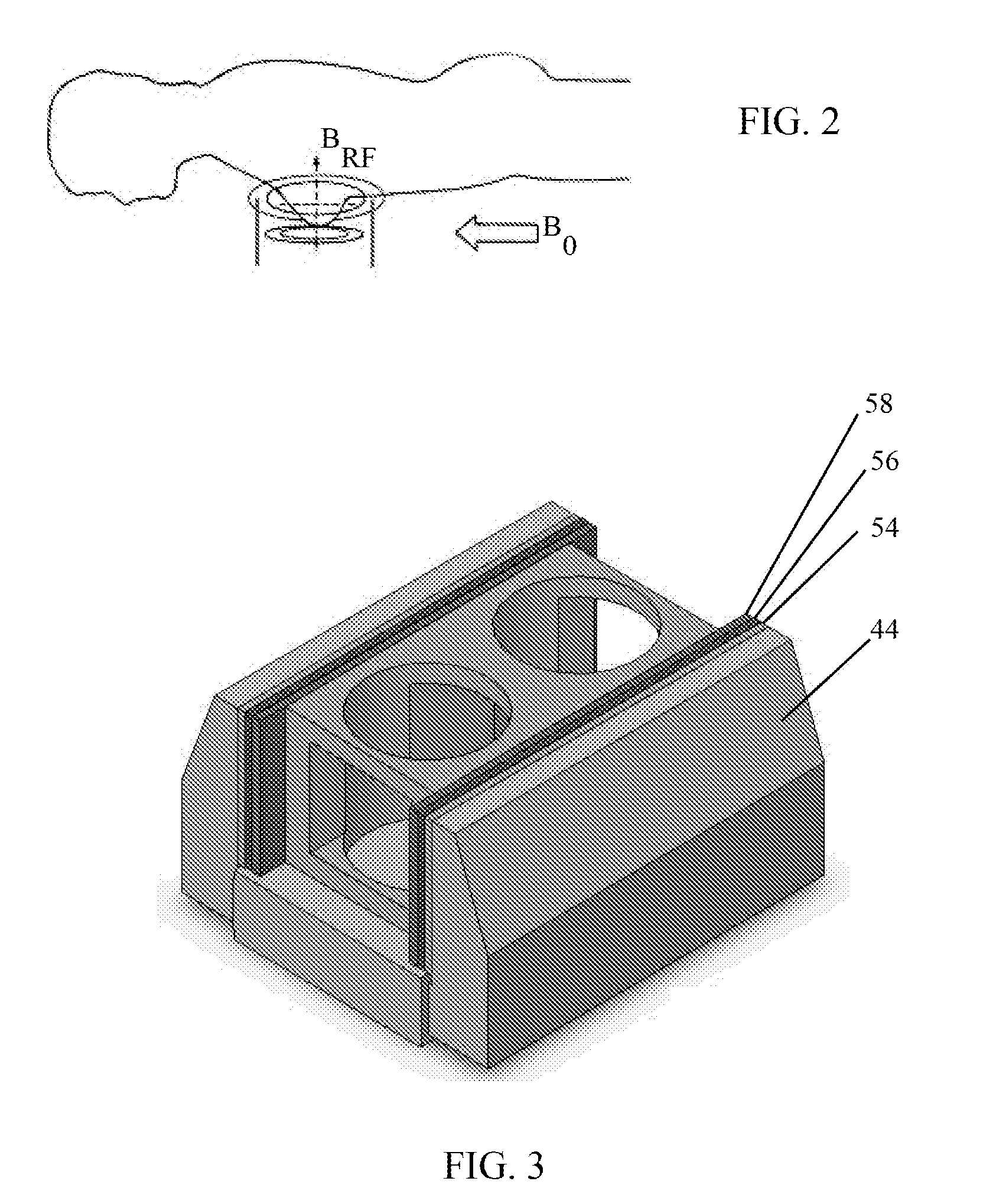
[0029]Reference is now made to FIG. 1, which illustrates apparatus for producing magnetic resonance (MR) images of a subject over a limited volume, constructed and operative in accordance with a non-limiting embodiment of the present invention.

[0030]FIG. 1 illustrates a simplified block diagram of a system for producing MR images in accordance with embodiments of the present invention. In the illustrated embodiment, the system is a MR imaging system designed for the stand-alone screening of breasts for anomalies. The MRI system could be, for example, adapted for performing breast biopsies. In another embodiment the MRI system can perform imaging and treatment of most other extremities.

[0031]The operation of the system is controlled from an operator console 12 consisting of a computer interface, including keyboard and control panel and a display. The console 12 communicates through links with a separate control and processor (also known as computer or control) system 14 that enables ...


PUM


Abstract

Apparatus for producing magnetic resonance (MR) images of a subject over a limited volume, including a patient table, and a shielded unit housed under the patient table, the shielded unit including an RF pulse generator module, a magnet assembly for producing a static magnetic field in magnetic structure including a shaped magnetic “C” core, a gradient field generating assembly for generating magnetic field gradients in two orthogonal planes for producing MR images, a radiofrequency (RF) coil assembly for transmitting a broad band radiofrequency pulse and a RF field matching structure to simulate an infinite volume to the RF coil assembly, wherein the RF coil assembly detects a plurality of MR signals induced from a subject in response to RF pulses from the RF pulse generator.

Description

CROSS-REFERENCE TO RELATED APPLICATIONS[0001]This application claims priority under 35 USC §119 to U.S. Provisional Patent Application 60 / 974,627, filed Sep. 24, 2007, which is incorporated herein by reference.FIELD OF THE INVENTION[0002]The present invention relates generally to a method and system for medical imaging, and particularly to a method and system for restricted volume imaging using a Magnetic Resonance Imaging (MRI) system, employing a stationary patient table and an electro magnetic field restricted to the area to be imaged. The present invention relates to imaging of the breast, in particular, and may extended to image extremities such as arms and legs or other constricted volumes like the prostrate. The system is an open structure allowing easy access to the imaged area for a hand guided biopsy or treatment.BACKGROUND OF THE INVENTION[0003]Nuclear magnetic resonance imaging (“MRI”) is utilized for scanning and imaging biological tissue as a diagnostic aid, and is one...

Claims


Application Information

Patent Timeline
Patent Type & Authority Applications(United States)
IPC IPC(8): A61B5/055G01R33/483
CPCA61B5/055G01R33/3806G01R33/383G01R33/56536G01R33/3875G01R33/4824G01R33/385
Inventor ISRAEL, HENRY M.
Owner ISRAEL HENRY M
Why Eureka
Try Eureka