Exhaust after-treatment system having a secondary tank

a technology of exhaust aftertreatment and secondary tank, which is applied in the direction of pipe heating/cooling, machines/engines, liquid transferring devices, etc., can solve the problems of thawing urea immediately, and affecting the thawing effect of reductan

Inactive Publication Date: 2009-04-02
CATERPILLAR INC
View PDF18 Cites 26 Cited by
  • Summary
  • Abstract
  • Description
  • Claims
  • Application Information

AI Technical Summary

Benefits of technology

[0008]Another aspect of the present disclosure is directed to a method of operating an exhaust after-treatment system. The method may include thawing reductant at a first location and at a second location. The method may additionally include directing reductant from the second location to the first location to facilitate the thawing of reductant at the first location.

Problems solved by technology

Although SCR can be effective, the reductant can be problematic in both cold and hot temperatures.
Specifically, urea at a 32% concentration has a freezing point of about −11° C. and, thus, may freeze and become useless in some environments.
However, after thawing the urea in the immediate vicinity of the heater, the thawed urea may immediately be consumed by the SCR process.
This air gap may act as an insulator and decrease the effectiveness of the heater in thawing the rest of the urea.
Additionally, urea may begin to decompose at a temperature of about 133° C. The decomposition of urea prior to passing through the SCR system may hinder the SCR process.
And, the '602 publication fails to address the problem of urea overheating.

Method used


Image

  • Exhaust after-treatment system having a secondary tank
  • Exhaust after-treatment system having a secondary tank
  • Exhaust after-treatment system having a secondary tank

Examples


Embodiment Construction

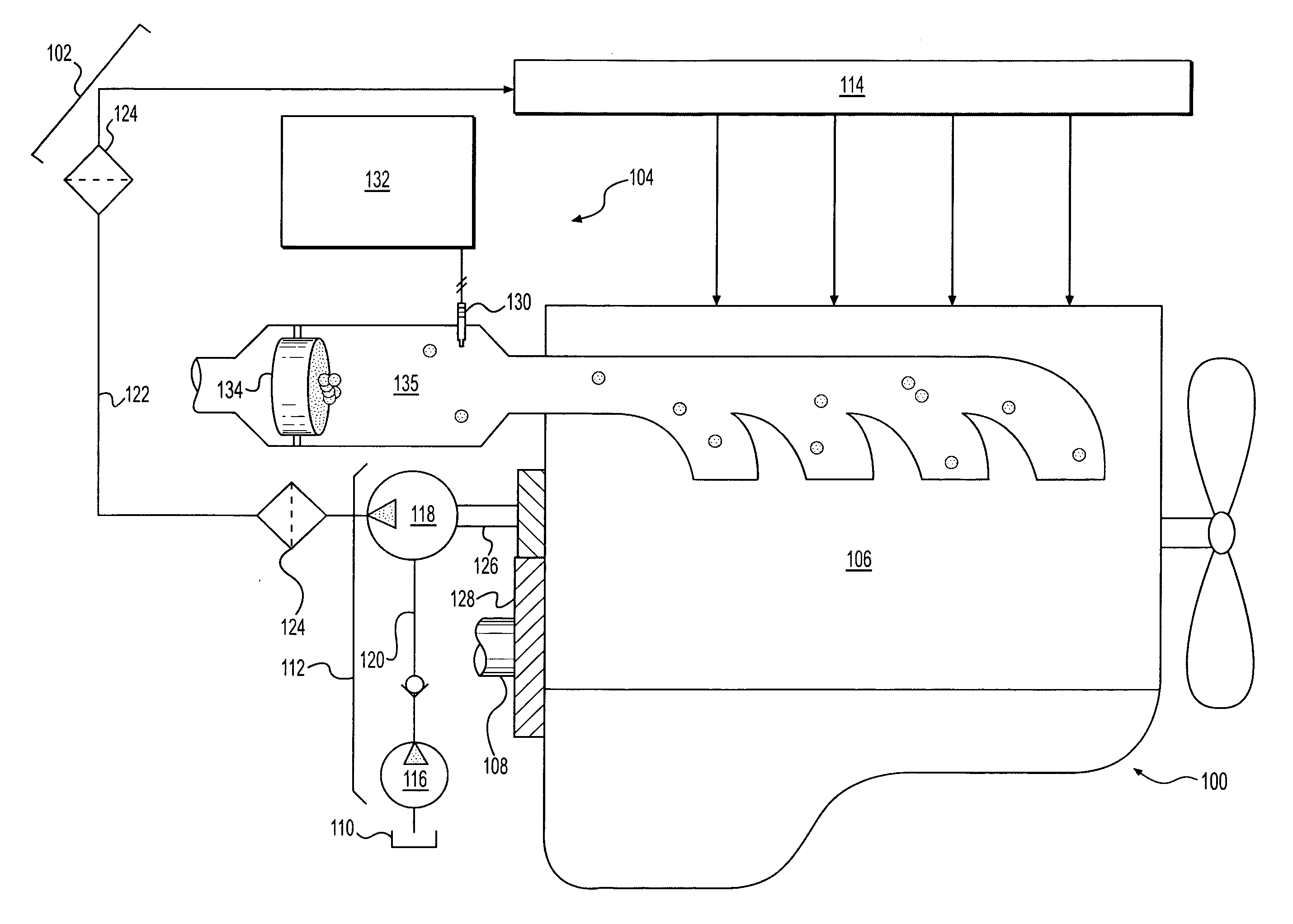
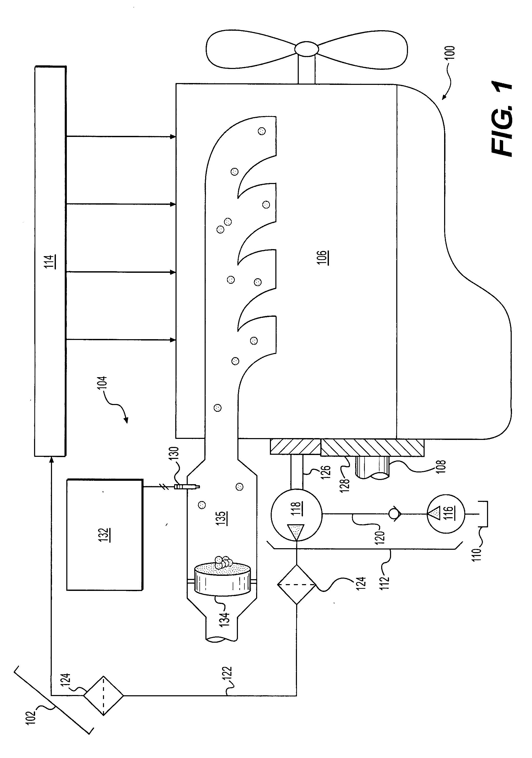
[0011]FIG. 1 illustrates a power unit 100. For the purposes of this disclosure, power unit 100 is depicted and described as a four-stroke diesel engine. One skilled in the art will recognize, however, that power unit 100 may be any other type of internal or external combustion engine, such as, for example, a gasoline or a gaseous fuel-powered engine. Power unit 100 may include an engine block 106 that at least partially defines a plurality of combustion chambers (not shown). In the illustrated embodiment, power unit 100 includes four combustion chambers. However, it is contemplated that power unit 100 may include a greater or lesser number of combustion chambers and that the combustion chambers may be disposed in an “in-line” configuration, a “V” configuration, or any other suitable configuration.

[0012]As also shown in FIG. 1, power unit 100 may include a crankshaft 108 that is rotatably disposed within engine block 106. A connecting rod (not shown) may connect a plurality of piston...


PUM


Abstract

An exhaust after-treatment system having a main tank configured to retain and supply a reductant is disclosed. The exhaust after-treatment system includes a main heat source disposed in the main tank and configured to thaw the reductant. The exhaust after-treatment system also includes a secondary tank configured to retain a supply of reductant and a pump configured to pass reductant from the secondary tank to the main tank. The exhaust after-treatment system further includes a secondary heat source configured to thaw the reductant within the secondary tank.

Description

TECHNICAL FIELD[0001]The present disclosure is directed to exhaust after-treatment system and, more particularly, to an exhaust after-treatment system having a secondary tank.BACKGROUND[0002]Internal combustion engines, including diesel engines, gasoline engines, gaseous fuel-powered engines, and other engines known in the art exhaust a complex mixture of air pollutants. These air pollutants are composed of gaseous compounds, such as, for example, the oxides of nitrogen (NOx). Due to increased awareness of the environment, exhaust emission standards have become more stringent, and the amount of NOx emitted from an engine may be regulated depending on the type of engine, size of engine, and / or class of engine. In order to ensure compliance with the regulation of these compounds, some engine manufacturers have implemented a strategy called Selective Catalytic Reduction (SCR). SCR is a process where a gaseous or liquid reductant (most commonly a urea / water solution) is added to the exh...

Claims


Application Information

Patent Timeline
Patent Type & Authority Applications(United States)
IPC IPC(8): F01N3/10
CPCF01N3/2066F01N2610/02Y02T10/24F01N2610/1406F01N2610/10Y02T10/12Y10T137/6606Y10T137/86187
Inventor DALTON, DALE ARNOLD
Owner CATERPILLAR INC
Why Eureka
Try Eureka