Planographic printing plate manufacturing apparatus

a technology of manufacturing apparatus and planographic printing plate, which is applied in the direction of printing, manufacturing tools, transportation and packaging, etc., can solve the problems of cracks, cracks in the treated layer on the surface of warped parts, and scratching of the lower surface of the cut web, so as to prevent the generation of burrs, prevent the formation of flaws, and suppress the effect of burrs

Inactive Publication Date: 2009-04-02
FUJIFILM CORP
View PDF3 Cites 11 Cited by
  • Summary
  • Abstract
  • Description
  • Claims
  • Application Information

AI Technical Summary

Benefits of technology

[0018]According to the present invention, the lower knife having the acute angle of 70° or more is used, and the level difference angle of the lower knife is set to 5° or less. Therefore, it is possible to prevent stain from being formed on the planographic printing plate, while securing a droop height on an upper surface of the planographic printing plate. At the same time, it is possible to suppress the generation of a burr, and to prevent a flaw from being caused at the time when the planographic printing plates are stacked. Note that the “droop height” in the present invention means an amount by which the upper surface of the planographic printing plate is lowered at the cutting position. Further, in the present invention, “up” and “down” represent a relative positional relation. When one of a pair of knives is set as an upper knife, and when the other of the pair of knives is set as a lower knife, the upper knife side is set as “up” and the lower knife side is set as “down”. Further, in the present invention, “cutting” means to cut a planographic printing plate in its thickness direction, and includes cutting (so-called slitting) a long-sized web in the longitudinal direction and cutting the long-sized web in the width direction and in an oblique direction.
[0019]According to the present invention, the angle at the boundary point between the decline part and the flat part is 135° or more, thereby it is possible to prevent the web from bending out at the point. The boundary point between the decline part and the cutting edge part is provided so as to have the distance from the cutting edge in the width direction of the web which is greater or equal to the droop width of the product lower surface. Therefore, the generation of the scratch flaw can be suppressed.

Problems solved by technology

However, in the method, when the level difference is increased to thoroughly prevent the burr from projecting from the web lower surface, the end of the web is largely warped downward, to cause a crack in the treated layer on the surface of the warped part.
This results in a problem of causing stain in the crack.
Also, there is a problem that the lower surface of the cut web is scratched by the lower knife depending on its shape.

Method used


Image

  • Planographic printing plate manufacturing apparatus
  • Planographic printing plate manufacturing apparatus
  • Planographic printing plate manufacturing apparatus

Examples


Embodiment Construction

[0029]In the following, a preferred embodiment of a planographic printing plate manufacturing apparatus according to the present invention will be described with reference to the accompanying drawings.

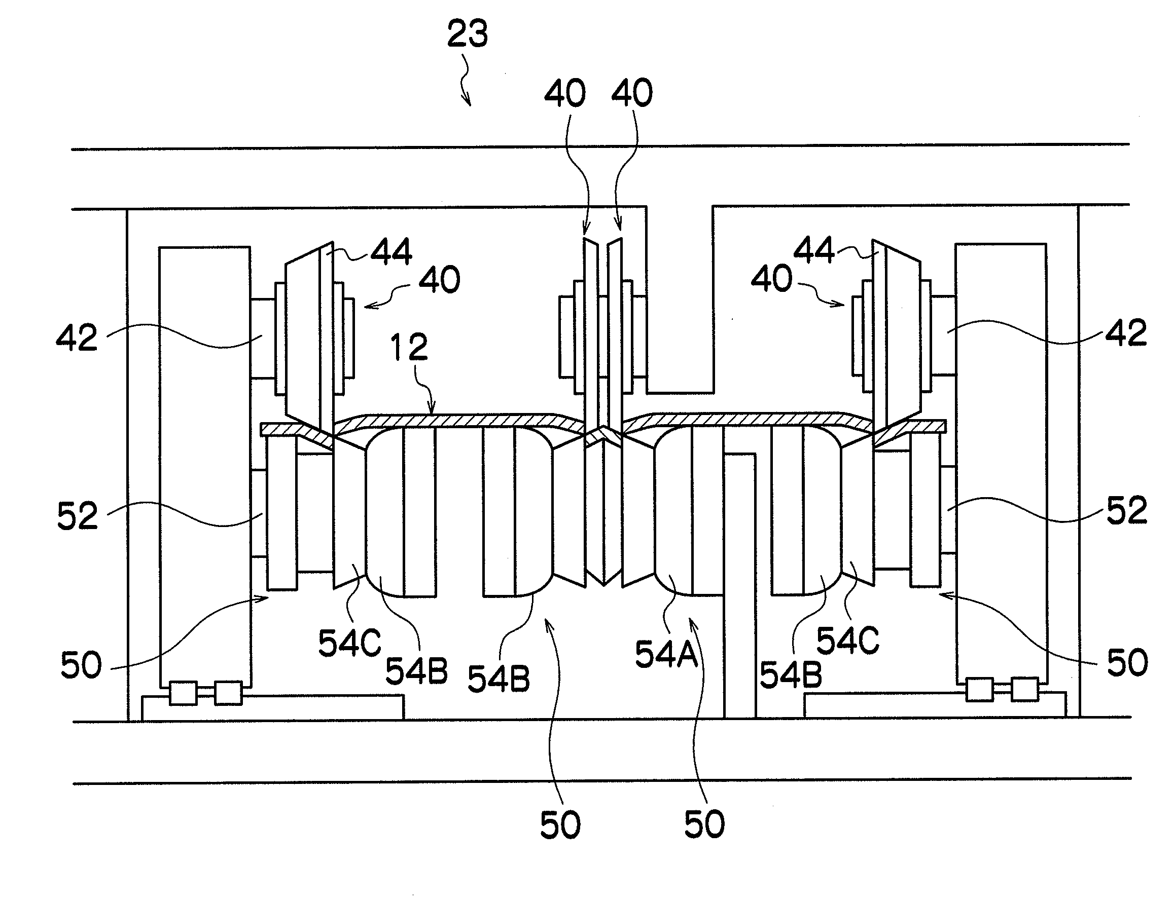
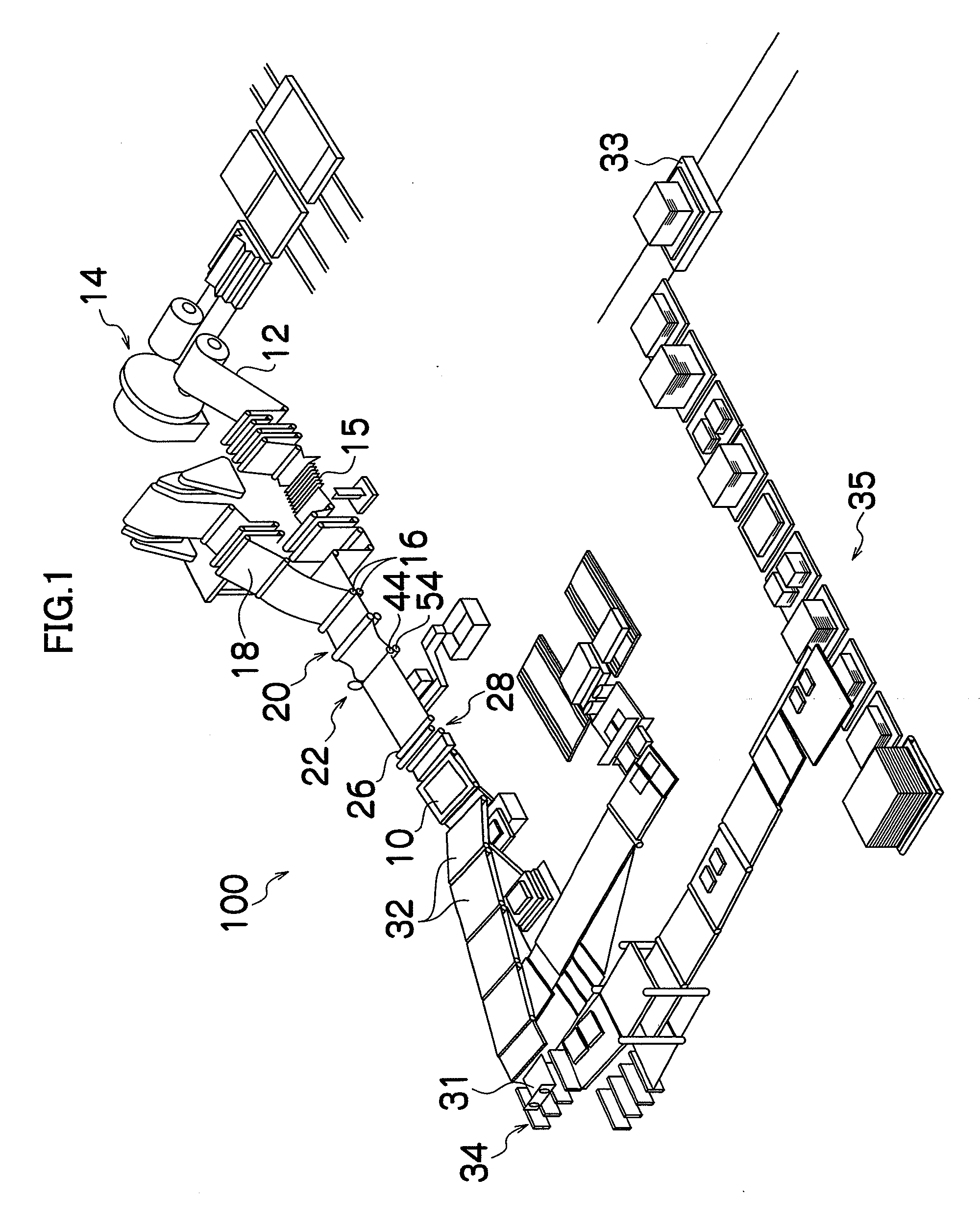
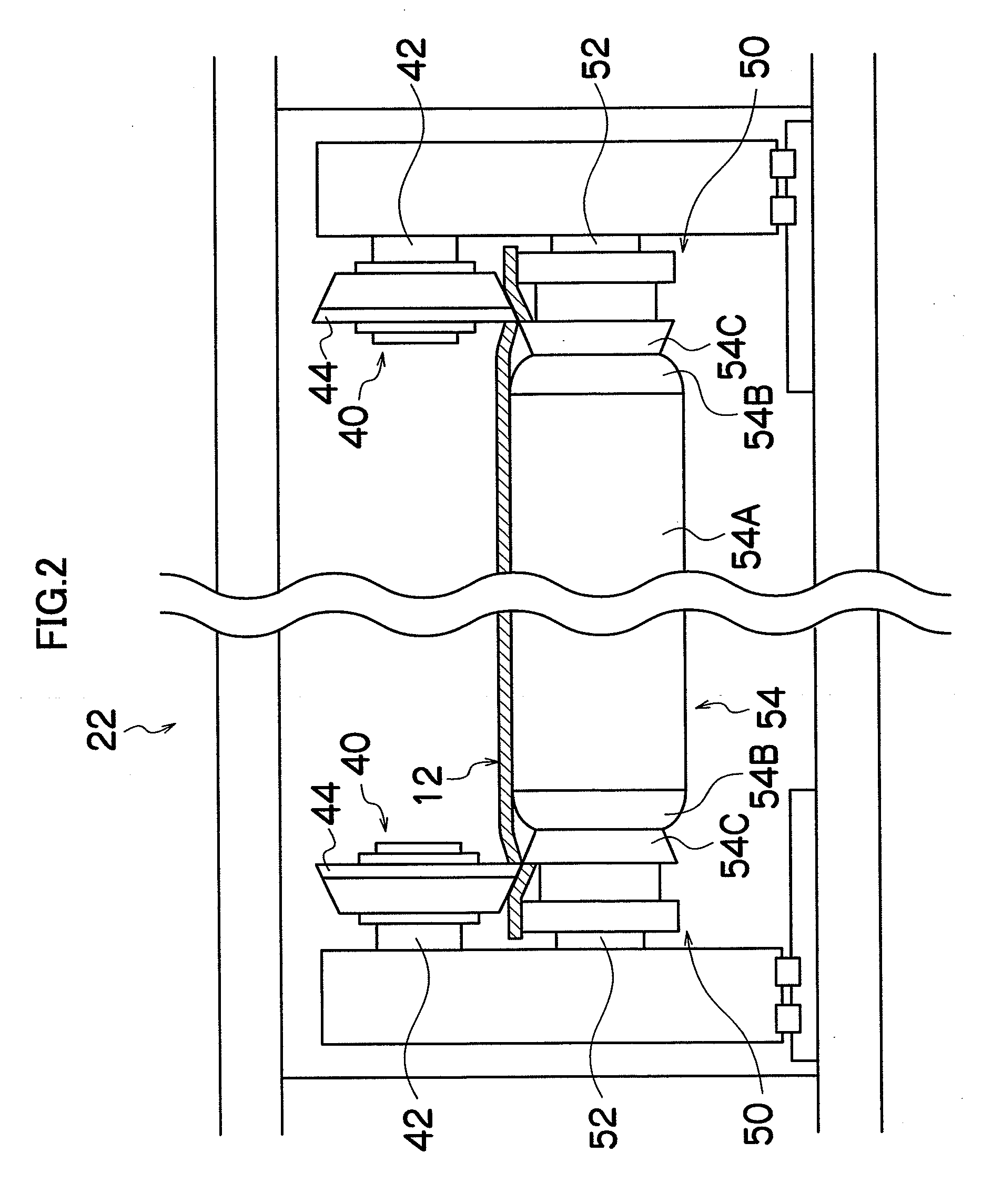
[0030]FIG. 1 is a perspective view showing a configuration of the planographic printing plate manufacturing apparatus according to the present embodiment, and shows a processing line 100 of a sheet-like planographic printing plate 10 (hereinafter referred to as PS plate 10).

[0031]As shown in FIG. 1, a feeder 14 is arranged in the upstream side (right upper side in FIG. 1) of the processing line 100. A web 12 wound in a rolled shape beforehand is loaded to the feeder 14, and the web 12 is successively wound out from the feeder 14.

[0032]The long-sized web 12 fed from the feeder 14 is subjected to curl correction by a leveler 15. Thereafter, the web 12 is bonded with an interleaving paper 18 at a position of feed rollers 16 and 16, so that they are tightly contacted with each other by ele...


PUM

PropertyMeasurementUnit
angleaaaaaaaaaa
level difference angleaaaaaaaaaa

Abstract

The present invention provides a planographic printing plate manufacturing apparatus comprising: a cutting process section which cuts a web in a thickness direction of the web by pinching the web with at least a pair of an upper knife and a lower knife, wherein the lower knife includes a flat part supporting a center of the web, a decline part gradually declined an upper end toward outside from the flat part and a cutting edge part having an upper end gradually raised toward outside from the decline part to be a cutting edge, an angle of the lower knife at a boundary point between the decline part and the flat part is 135° or more, a boundary point between the decline part and the cutting edge part is provided so as to be greater or equal to a droop width of a lower surface of a cut product.

Description

BACKGROUND OF THE INVENTION[0001]1. Field of the Invention[0002]The present invention relates to a planographic printing plate manufacturing apparatus, and more particularly, to a photosensitive planographic printing plate manufacturing apparatus.[0003]2. Description of the Related Art[0004]In the engraving method (including the electronic photoengraving method) in recent years, planographic printing plates, such as a photosensitive printing plate and a heat sensitive printing plate, have been widely used in order to facilitate automation of a plate making process. The planographic printing plate is generally manufactured by such a way that a supporting body such as a sheet-like or coil-like aluminum plate is surface-treated by a separate process, such as for example, a graining process, an anodic oxidation process, a silicate process, an other chemical conversion process, or by properly combining these processes, and that the surface-treated supporting body is then coated with a ph...

Claims


Application Information

Patent Timeline
Patent Type & Authority Applications(United States)
IPC IPC(8): B23D19/06
CPCB23D19/06B65H35/02B41C1/1083B23D35/001Y10T83/7809Y10T83/7813
Inventor ANNOURA, YASUHIRO
Owner FUJIFILM CORP
Why Eureka
Try Eureka