Stainless steel hatch and method of manufacture

Inactive Publication Date: 2009-04-02
POMPANETTE
View PDF3 Cites 0 Cited by
  • Summary
  • Abstract
  • Description
  • Claims
  • Application Information

AI Technical Summary

Benefits of technology

[0012]In one embodiment, at least one flexible mandrel is attached to the bar stock for reducing distortion of the fabricated base, prior to the bending step. In an alternative embodiment, the cutting step occurs after the bending step.

Problems solved by technology

The outer surface is often mirror finished, while the underside of the deck is typically raw and unfinished.
In contradistinction to aluminum boat hatches, hatches fabricated from stainless steel have not been used in volume production boat building, and rarely in boat building at all, because of the rigid properties of stainless steel, and concomitant higher manufacturing costs.
Stainless steel hatch bases may be fabricated, but they normally require considerably more time to manufacture and install, which translates into substantially higher costs.
However, such earlier methods resulted in excessive visual distortion in the hatch base having a traditional cross-section, a spigot is was not included as an integral part of the hatch base.
Consequently, a trim ring could not be used because there was no spigot with which to engage.
Instead, the boat builder would custom design, craft, and install a trim ring substitute, which drastically raised production time, and therefore, costs making them economically unattractive.
Accordingly, stainless steel for use in marine hatches has not been considered an acceptable material for production boat building, and has been reserved primarily for use by specialty boat builders.
To date, there have been no stainless steel hatch bases available which included spigots.
This traditional shape, when made from thin walled stainless steel, results in too much flaring, or distortion, of the flange and / or spigot after bending to be acceptable for use in the marine industry.
A distorted hatch frame is not aesthetically attractive and also results in an engagement with the trim ring which is not uniform or constant.

Method used


Image

  • Stainless steel hatch and method of manufacture
  • Stainless steel hatch and method of manufacture
  • Stainless steel hatch and method of manufacture

Examples


Embodiment Construction

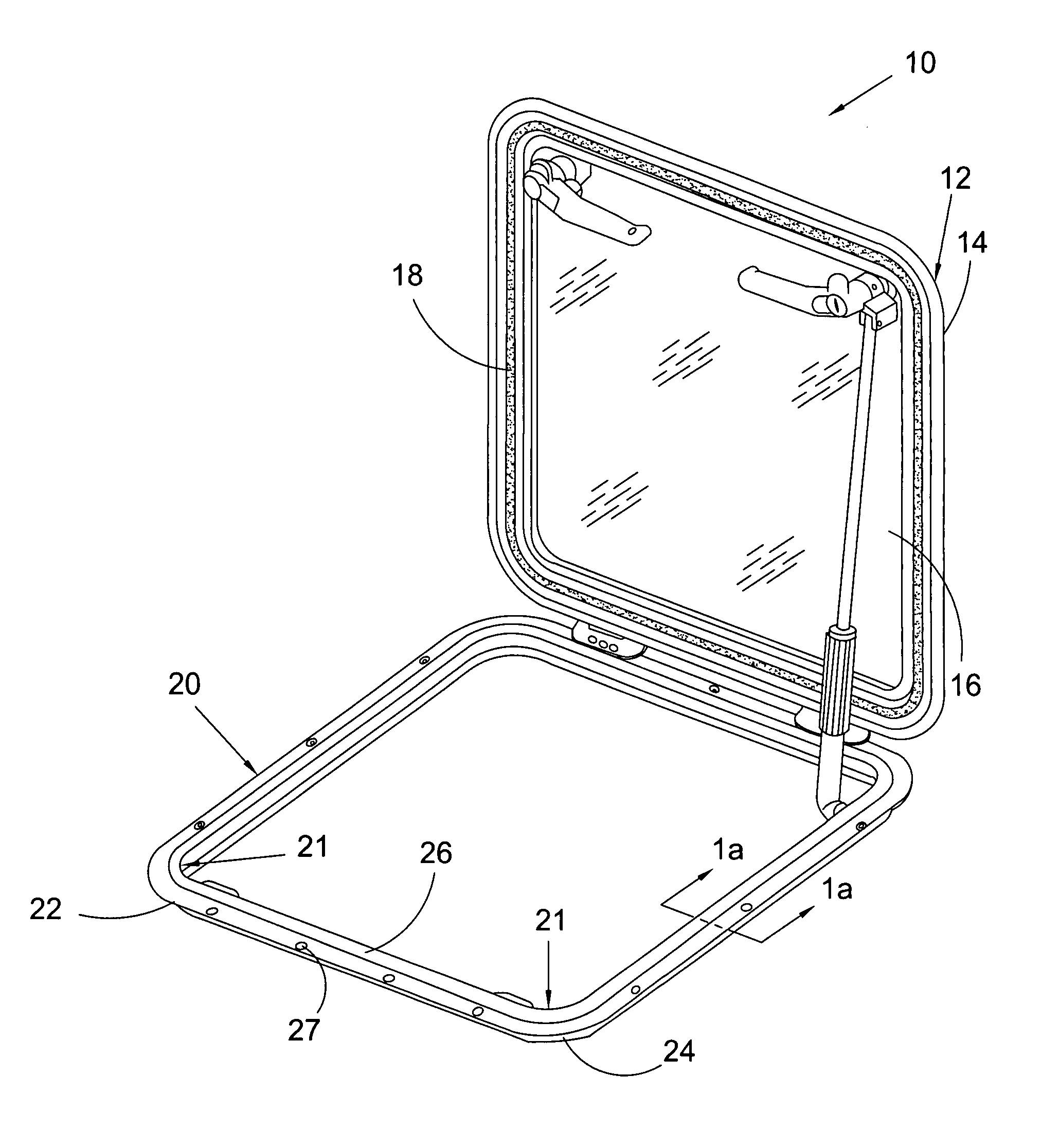
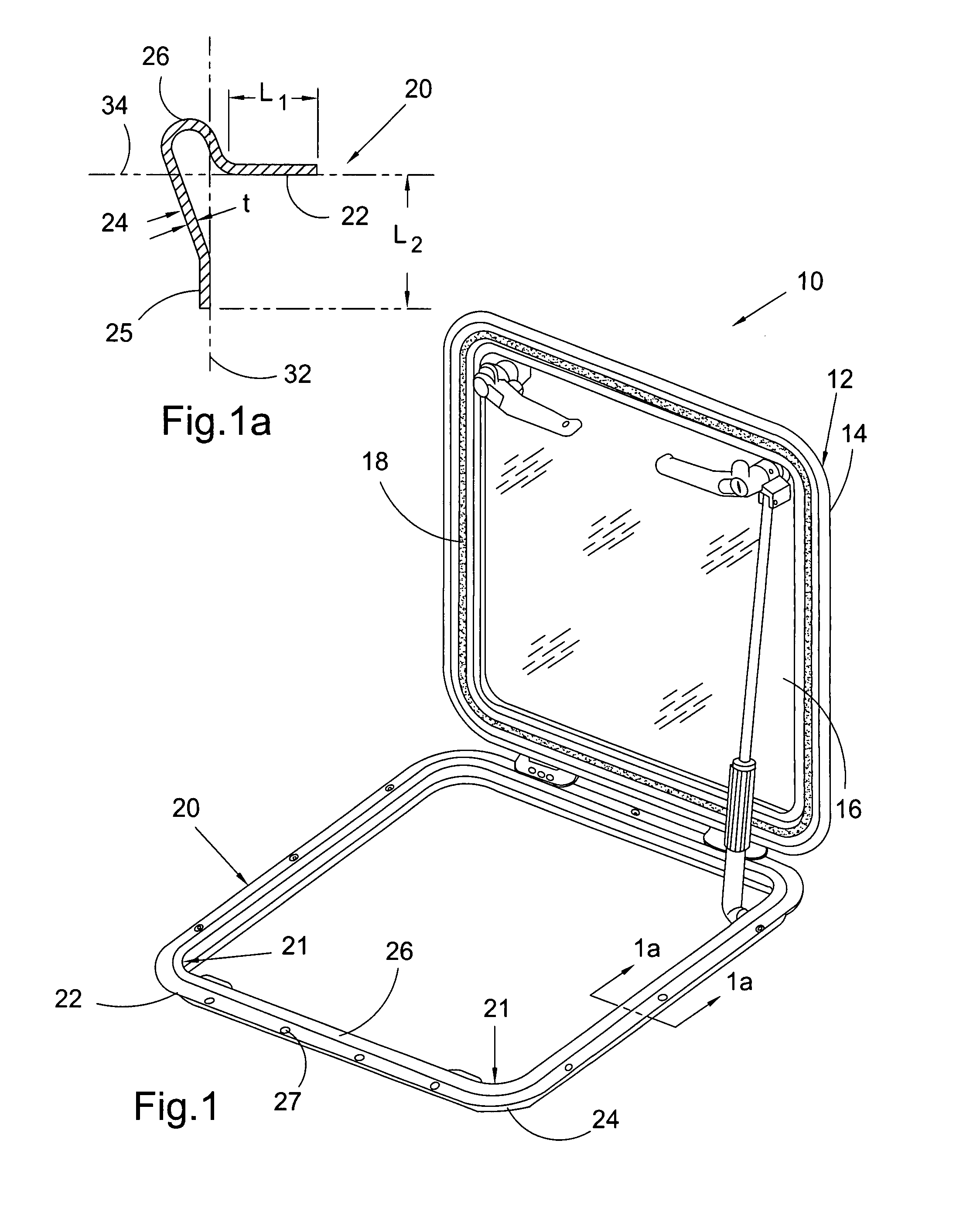
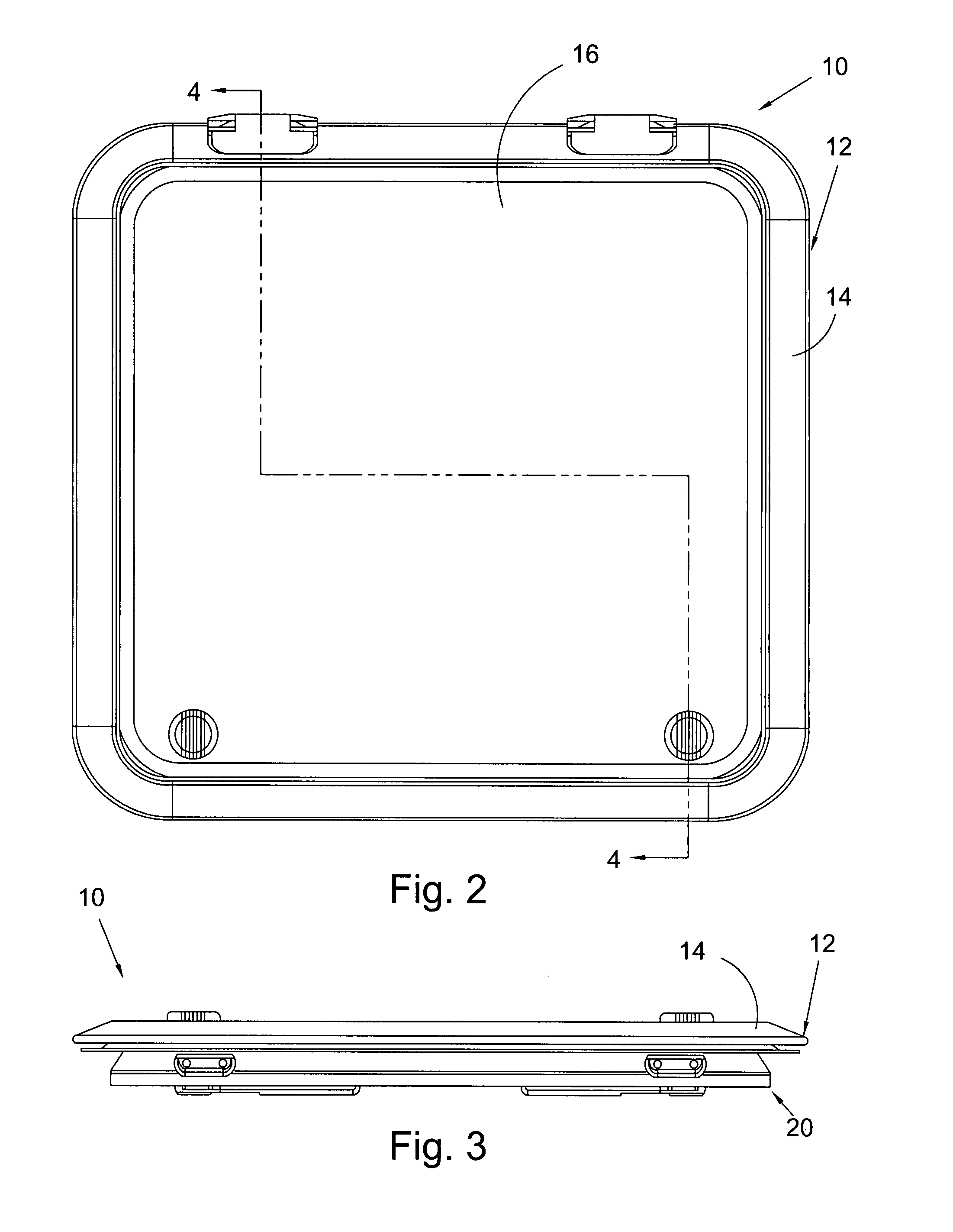
[0024]At the outset, it should be appreciated that while the present invention is described with respect to what is presently considered to be the preferred embodiments, the invention is not limited to the embodiments specifically recited herein. In the detailed description that follows like drawing numbers on different drawing views are intended to identify identical structural elements of the invention. Also, the adjectives, “front,”“back,”“left,”“right,”“top,” and “bottom” and their derivatives, in the description herebelow, refer to the perspective of one facing the invention as it is shown in the Figure under discussion.

[0025]Furthermore, it should be understood that this invention is not limited to the particular methodology, materials and modifications described and as such may, of course, vary. It should also be understood that the terminology used herein is for the purpose of describing particular aspects only, and is not intended to limit the scope of the present invention...


PUM

PropertyMeasurementUnit
Lengthaaaaaaaaaa
Lengthaaaaaaaaaa
Radiusaaaaaaaaaa

Abstract

A base for a marine hatch including a planar exterior flange running in a plane substantially parallel with a boat hull or deck, an angular leg running generally transverse to the planar exterior flange, the angular leg terminating in a spigot, wherein the spigot is substantially perpendicular to the exterior planar flange, the spigot is operatively positioned so that the spigot runs substantially parallel to a neutral bending axis, and the neutral bending axis passes through or is directly proximate the spigot, and an elevated sealing bead for engaging with a hatch cover, the planar exterior flange and the angular leg being integral with the elevated sealing bead.

Description

FIELD OF THE INVENTION[0001]The present invention relates to hatches, and more particularly, to improved marine hatches and methods of manufacturing the same.BACKGROUND OF THE INVENTION[0002]Hatches, particularly hatches for boats, are fairly well known devices that allow ingress and egress into and out of enclosed areas, e.g., boat cabins, and / or allow light to enter an enclosed area. Deck hatches are available in many sizes, from small ventilation hatches to larger hatches used as emergency exit points. A ventilation hatch might be as small as 12×12 inches, where as a typical large hatch intended for persons and objects to pass through might be 20×20 inches. Hatches, thus, generally comprise assemblies that allow entry, exiting and closure, generally comprise a cover, a base, hinge means connecting the cover and the base, and a gasket means between the cover and the base to ensure a water-tight seal. Hatches may be installed on boat hulls and decks. Standard production boats typic...

Claims


Application Information

Patent Timeline
IPC IPC(8): B63B19/14B21B1/00
CPCB63B19/21Y10T29/49826B63B19/26
Inventor KYLE, JAMES H.
Owner POMPANETTE
Why Eureka
Try Eureka