Self-poling piezoelectric MEMS device

a piezoelectric and self-poling technology, applied in micro-structural devices, relays, generators/motors, etc., can solve the problems of low currie temperature of piezoelectric materials, degrade device performance, and high undesirable effects

Inactive Publication Date: 2009-04-02
FREESCALE SEMICON INC
View PDF8 Cites 11 Cited by
  • Summary
  • Abstract
  • Description
  • Claims
  • Application Information

AI Technical Summary

Problems solved by technology

However, these piezoelectric materials have some critical draw backs: 1) the film of piezoelectric material needs to be electrically poled in order to have a usable piezoelectric prope

Method used


Image

  • Self-poling piezoelectric MEMS device
  • Self-poling piezoelectric MEMS device
  • Self-poling piezoelectric MEMS device

Examples


Embodiment Construction

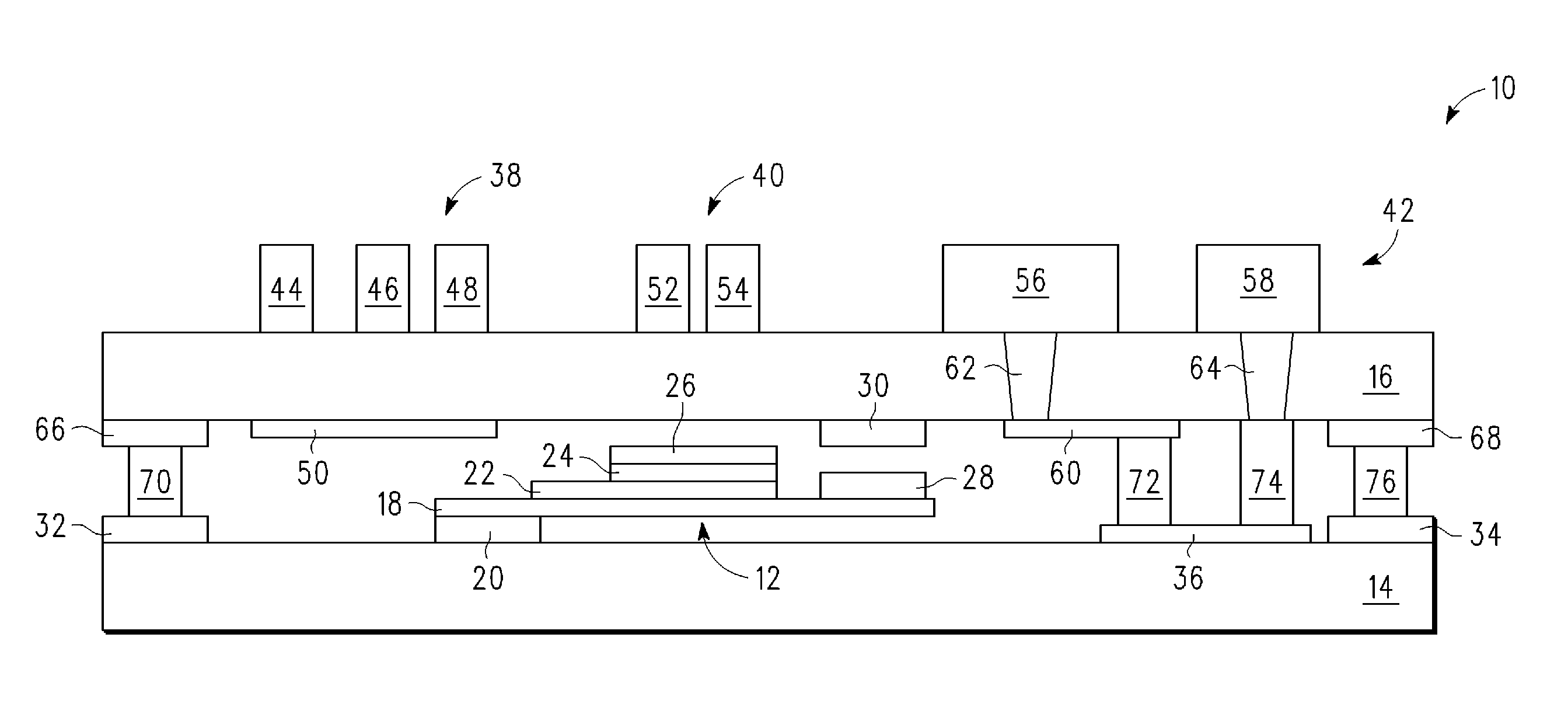
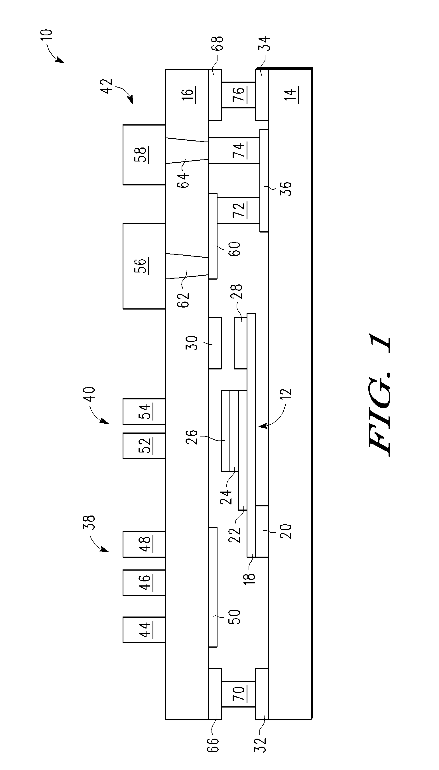
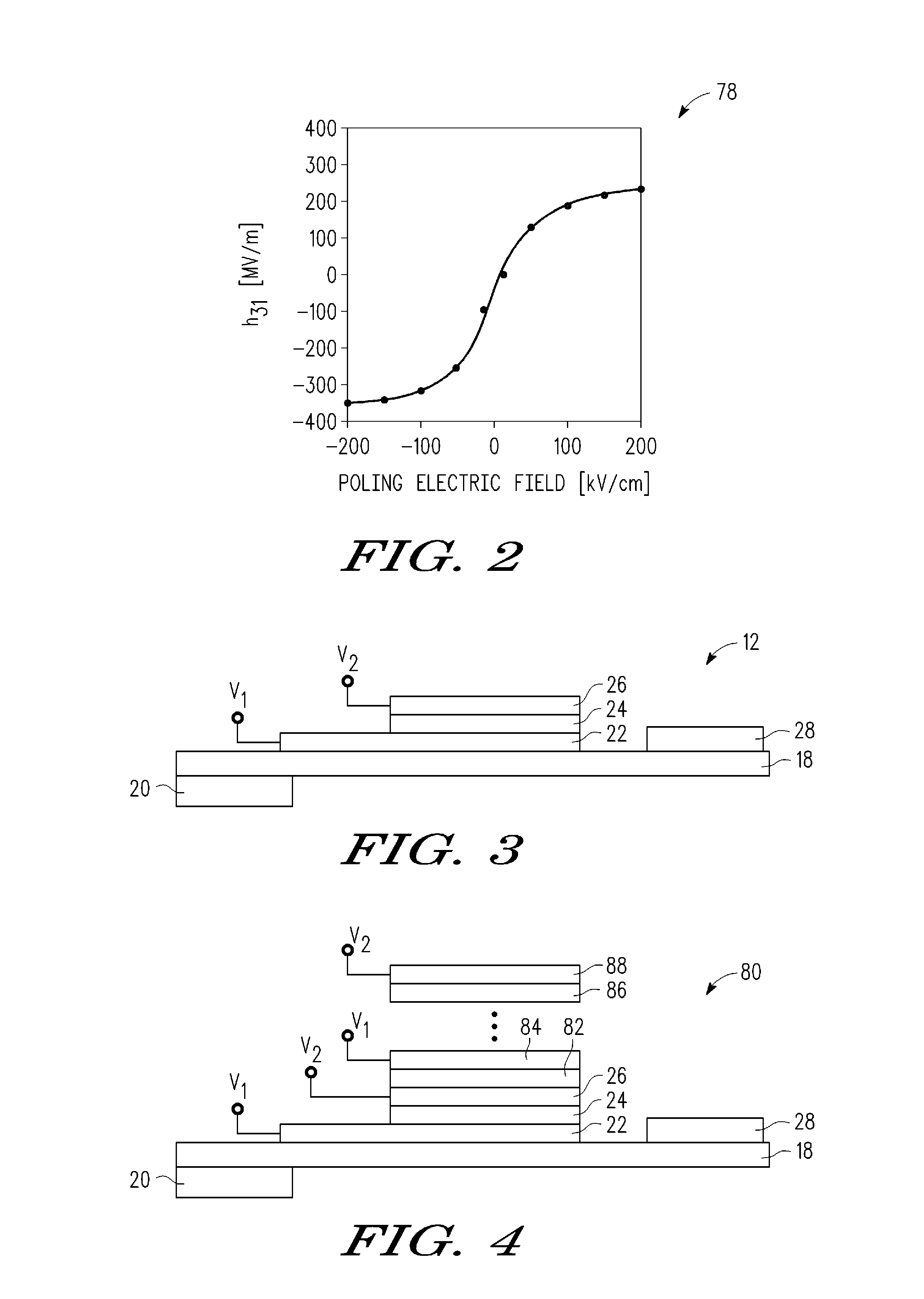
[0012]The embodiments of the present disclosure are directed to MEMS devices which use piezoelectric material and its property, wherein the piezoelectric layer thickness is selected to be in a self-poling thickness range so that the poling field strength at the resultant device operating voltage exceeds a required poling field (for example, on the order of more than 100 to 150 KV / cm for PZT at room temperature) when the device operation voltage is applied to the device.

[0013]In addition, the embodiments of the present disclosure provide a self-poling piezoelectric film actuating MEMS device. That is, instead of poling a piezoelectric film before the MEMS device is assembled into a PCB board or other electronic system, the MEMS device is self-poled during one or more of the following: 1) a power-on stage of the electronic system in which the piezoelectric MEMS device is incorporated, and / or 2) a normal operation of the same system, by i) the device operating voltage and / or ii) anothe...


PUM


Abstract

A self-poling piezoelectric based MEMS device is configured for piezoelectric actuation in response to application of a device operating voltage. The MEMS device comprises a beam, a first electrode disposed on the beam, a layer of piezoelectric material having a self-poling thickness disposed overlying a portion of the first electrode, and a second electrode overlying the layer of piezoelectric material. The layer of piezoelectric material is self-poled in response to application of the device operating voltage across the first and second electrodes. In addition, the self-poled piezoelectric material has a poling direction established according to a polarity orientation of the device operating voltage as applied across the first and second electrodes.

Description

BACKGROUND [0001]1. Field[0002]This disclosure relates generally to micro electromechanical system (MEMS) devices, and more specifically, to self-poling piezoelectric MEMs devices.[0003]2. Related Art[0004]MEMS devices using piezoelectric thin films are attracting more and more attention, partly due to the fact that such devices enable low voltage operation and can easily convert electrical energy to mechanical energy or vice versa. One family of materials, namely perovskite type ceramics such as PZT, is particularly notable for its high piezoelectric constants. However, these piezoelectric materials have some critical draw backs: 1) the film of piezoelectric material needs to be electrically poled in order to have a usable piezoelectric property; and 2) the Currie Temperature of these piezoelectric materials is low. For example, PZT has a Currie Temperature (Tc) of around 360° C. At temperatures above one half of the PZT film's Currie Temperature (Tc / 2), which corresponds to a appr...

Claims


Application Information

Patent Timeline
IPC IPC(8): H01L41/09H01L41/083H01L41/187
CPCB81B3/0086B81B2201/0235B81B2203/0118H01H2057/006H01L41/094H01L41/257H01H57/00H10N30/2042H10N30/045
Inventor LIU, LIANJUN
Owner FREESCALE SEMICON INC
Why Eureka
Try Eureka