Power Supply Device, Electronic Device, and A/D Converter Used for Them

a technology of power supply device and electronic device, which is applied in the direction of code conversion, instruments, process and machine control, etc., can solve the problems of unnecessarily high boost ratio, deterioration of efficiency, and decrease of the efficiency of the charge pump circui

Inactive Publication Date: 2009-04-02
ROHM CO LTD
View PDF7 Cites 26 Cited by
  • Summary
  • Abstract
  • Description
  • Claims
  • Application Information

AI Technical Summary

Benefits of technology

[0013]According to this embodiment, it is possible to appropriately set the boost ratio based on the input voltage to the power supply apparatus.
[0035]According to this embodiment, it is possible to perform A / D conversion of the analog signal inputted from the sensor, using the A / D converter used in the power supply apparatus, and to output the signal. Even in cases in which voltage fluctuations of the analog signal from the sensor are small, since it is possible to perform A / D conversion with high accuracy, there is no need to prepare a separate A / D converter for the sensor, and it is possible to configure a small-sized, low-cost electronic device.

Problems solved by technology

However, since, in general, efficiency of the charge pump circuit decreases as the boost ratio becomes high, the efficiency deteriorates more with the latter.
When the high voltage is outputted after outputting the low voltage, in cases in which the output voltage is monitored, there is a possibility that the boost ratio will be set unnecessarily high.
In this way, when setting the boost ratio of the charge pump circuit, in cases in which the output voltage is monitored, there is a risk that the efficiency will be needlessly worsened.
Furthermore, in cases in which the output voltage of the charge pump circuit is turned ON and OFF time-wise, there is a problem in that the boost ratio cannot be properly set, in a period until the output voltage of the charge pump circuit is stabilized.

Method used


Image

  • Power Supply Device, Electronic Device, and A/D Converter Used for Them
  • Power Supply Device, Electronic Device, and A/D Converter Used for Them
  • Power Supply Device, Electronic Device, and A/D Converter Used for Them

Examples


first embodiment

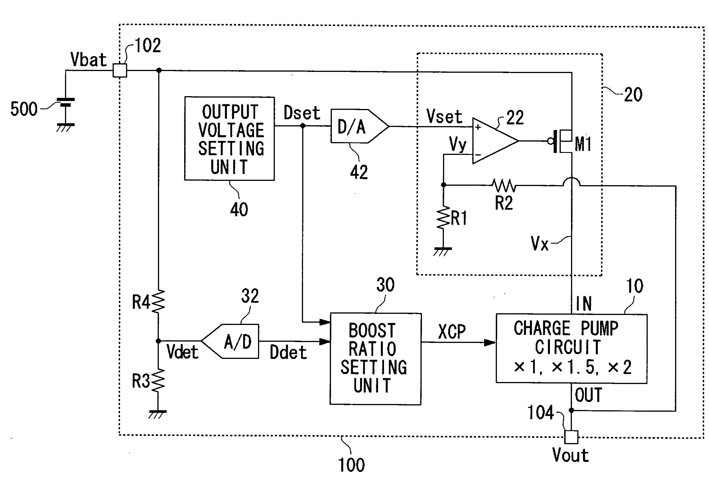
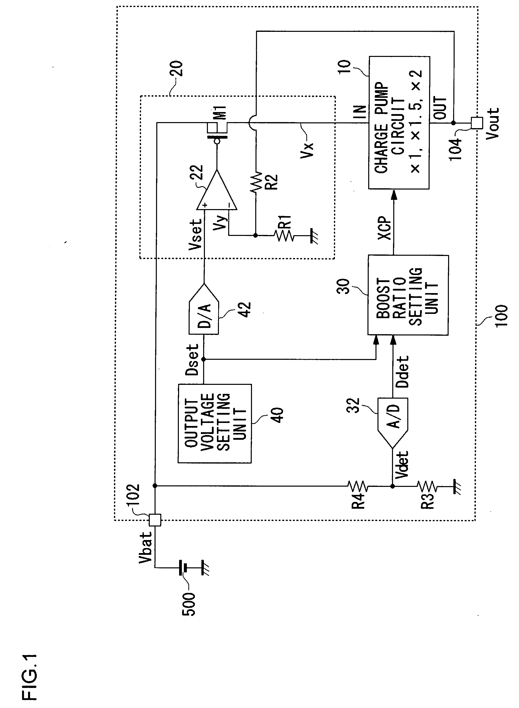
[0060]FIG. 1 is a circuit diagram showing a configuration of a power supply apparatus 100 according to a first embodiment of the present invention. This power supply apparatus 100 is installed in a small sized information terminal that is driven by a battery 500, and with a battery voltage Vbat outputted from the battery 500 as an input voltage, the battery voltage Vbat is boosted and voltage necessary for driving a load circuit is generated.

[0061]As input and output terminals, the power supply apparatus 100 is provided with an input terminal 102 and an output terminal 104. The battery voltage Vbat outputted from the battery 500 is applied to the input terminal 102. A load circuit, not shown in the figure, is connected to the output terminal 104. The power supply apparatus 100 boosts the battery voltage Vbat applied to the input terminal 102, and outputs an output voltage Vout from the output terminal 104.

[0062]The power supply apparatus 100 includes a charge pump circuit 10, a volt...

second embodiment

[0086]A power supply apparatus according to a second embodiment boosts battery voltage Vbat, and drives a light emitting diode of three colors RGB. The three color light emitting diode is alternately lit by carrying out time division. Since an optimal voltage for driving the light emitting diode differs for each respective RGB color, the power supply apparatus changes an output voltage set value each time a light emitting diode, that is lit, is switched, and a boost ratio of a charge pump circuit is set to an optimal value.

[0087]FIG. 3 is a circuit diagram showing a configuration of a light emitting device according to the present embodiment. In FIG. 3, component elements that are the same as, or equivalent to, those in FIG. 1 are given the same reference symbols, and explanations are omitted as appropriate. The light emitting device 1000 includes a battery 500, a power supply apparatus 100, light emitting diodes 300R to 300B that have three colors RGB, and a drive controller 400 wh...

third embodiment

Premise Regarding Third Embodiment

[0102]In small sized electronic devices, such as mobile telephones, PDAs (Personal Digital Assistants), digital cameras, and the like, in order to monitor and control, by microprocessor, temperature inside the device, voltage of a battery, or the like, an A / D converter is used which converts an analog signal thereof to a digital signal.

[0103]In cases in which a plurality of analog signals are processed, there is problem with regard to cost in preparing the A / D converter for the number of signals thereof. Furthermore, particularly in cases of small sized electronic devices, there is a problem in circuit size becoming large. Accordingly, conventionally, in cases in which A / D conversion is performed on the plurality of analog signals, there is a method in which a multiplexor is used to switch the plurality of analog signals in a time division manner, and convert into digital signals, sequentially by one A / D converter (for example, Japanese Patent Appli...


PUM


Abstract

In the power supply apparatus which performs voltage conversion of an input voltage (Vbat), with a predetermined set voltage as a target value, and outputs the converted voltage, a boost ratio setting unit sets a boost ratio (XCP) of the charge pump circuit based on the input voltage (Vbat) and a predetermined set voltage. A voltage adjustment unit is a regulator circuit, and adjusts voltage (Vx) so that output voltage (Vout) of the charge pump circuit approaches the set voltage. An output voltage setting unit generates a predetermined set voltage as a digital value (Dset). An A / D converter performs analog-digital conversion of the input voltage (Vbat). The boost ratio setting unit sets the boost ratio based on a result of comparing an input voltage (Ddet) that has undergone analog-digital conversion, and the set voltage (Dset).

Description

1. FIELD OF THE INVENTION[0001]The present invention relates to a power supply apparatus, and in particular, to control technology for a charge pump circuit whose boost ratio can be switched.2. DESCRIPTION OF THE RELATED ART[0002]In recent years, among small sized information terminals such as mobile telephones, PDAs (Personal Digital Assistants) and the like, there are devices in which a voltage is required that is higher than an output voltage of a battery, as in, for example, a Light Emitting Diode (referred to as LED below) used as a backlight for liquid crystal, and the like. In many of these small sized information terminals, Li-ion batteries are used; the output voltage thereof is normally about 3.5 V, and, when fully charged, about 4.2 V, but the LED requires, as a drive voltage thereof, a voltage higher than the battery voltage. In this way, in cases in which a voltage higher than the battery voltage is required, the battery voltage is boosted using a boosting power supply ...

Claims


Application Information

Patent Timeline
Patent Type & Authority Applications(United States)
IPC IPC(8): G05F1/00
CPCH02M3/07H05B33/0815H02M2001/0045H05B45/38H02M1/0045
Inventor MIGUCHI, MITSUAKICHIDA, TAISUKEEZAKI, GO
Owner ROHM CO LTD
Why Eureka
Try Eureka